Categories
Cylinder Head & Valve Train

nsxb06021a.pdf

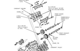
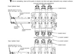
Cylinder Heads Illustrated Index CAUTION: To avoid damage, wait until the engine coolant temperature drops below 100°F (38°C) before removing the cylin- der head. NOTE: Use new O-rings and gaskets when reassembling. Prior to reassembling, clean all the parts in solvent, dry them, and apply lubricant to any contact parts. 6 x 1.0 mm 10N-m […]

Categories
Body

nsxd20050a.pdf

Dashboard Component Removal/Installation Clock and center air vent removal: NOTE: Take care not to scratch the dashboard and related parts. 1. Remove the clock by pulling it backward from the center air vent, then disconnect the connector. 2. Remove the center air vent mounting screws. Disconnect the connector. CLOCK CENTER AIR VENT CENTER AIR VENT […]

Categories
Construction & Function

nsxd05019a.pdf

Engine Removal/Installation Make sure jacks and safety stands are placed proper- ly and hoist brackets are attached to the correct positions on the engine (see section 1). Make sure the car will not roll off stands and fall while you are working under it. 3. Remove the expansion tank cap to speed draining. Use care […]

Categories
Automatic Transmission

nsxd14141a.pdf

1st-hold Clutch Bearing Replacement 1. Remove the 1st-hold clutch bearing using a bearing puller. BEARING PULLER 1ST-HOLD CLUTCH BEARING 1ST-HOLD CLUTCH 2. Install a new bearing using the special tools as shown. NOTE: Drive in the bearing until it fully bottoms. DRIVER 07749–0010000 ATTACHMENT, 72 x 75 mm 07746–0010600 Attachments nsxd14141a (125 kB)

Categories
Electrical

nsxd23288a.pdf

Wipers/Washers Windshield Wiper/Washer Switch Test 1. Remove the dashboard lower cover (see page 23-126). 2. Disconnect the 18-P connector from the floor wire harness. 3. Check for continuity between the terminals in each switch position according to the table. 18-P CONNECTOR WINDSHIELD WIPER/WASHER SWITCH View from wire side Attachments nsxd23288a (151 kB)

Categories
Cylinder Head & Valve Train

nsxd06035a.pdf

RUBBER BAND WASHERS EXHAUST ROCKER Replace. SHAFT INTAKE ROCKER SHAFT Rear Cylinder Head: SEALING BOLTS 20 mm 60N.m (6.0 kg-m, 43 Ib-ft) INTAKE ROCKER SHAFT WASHERS Replace. EXHAUST ROCKER SHAFT Front Cylinder Head: SEALING BOLTS 20 mm 60N.m (6.0 kg-m, 43 Ib-ft) RUBBER BAND EXHAUST ROCKER ARM ASSEMBLIES Rocker Arms and Shafts Locations Identify parts […]

Categories
Fuel & Emissions

nsxe11078a.pdf

Idle Control System Troubleshooting Flowchart M/T Neutral Switch Signal This signals the PGM-FI ECU when the transmission is in Neutral. Inspection of M/T neutral Switch Signal Connect the ECU test harness between the ECU and connector (page 11-21). 0V 10V B7 A26 Turn the ignition switch ON. Measure voltage between B7 (+) terminal and A26 […]

Categories
Heating, Ventilation and Air Conditioning

nsxb22079a.pdf

Replacement 1. Disconnect the negative cable from the battery. 2. Remove the from bumper (see section 20). 3. Recover the refrigerant using a R-134a refrigerant Recover/Recycling/Charging System (see page 22-73). 4. Disconnect the discharge line C and the condenser lines from the condenser. Cap the open fittings immediately to keep moisture and dirt out of […]

Categories
Electrical

nsxb23208a.pdf

G551 ’93-’96 Models )G551 ’93-’96 Models) Back-up Lights Test Manual Transmission: 1. If only one back-up right does not go on, check that bulb in the taillight. 2. If neither back-up light goes on, check the No. 5 (15 A) fuse in the under-dash fuse box. 3. If the fuse and bulbs are OK, disconnect […]

Categories
Uncategorized

nsx17index.pdf

Steering (’91−’94 Models) *: Read SRS precautions before working in this area Special Tools 17−2. . . . . . . . . . . . . . . . . . Manual Steering Component Location Index 17−18. . . . . . . . . . . . . System Description Steering Column 17−3. […]