Make sure jacks and safety stands are placed proper-
ly and hoist brackets are attached to the correct
positions on the engine (see section 1).
Make sure the car will not roll off stands and fall
while you are working under it.
3. Remove the expansion tank cap to speed draining.
Use care when removing the expan-
sion tank cap to avoid scalding by hot engine
coolant or steam.
4. Raise the hoist to full height.
5. Drain the engine coolant (see section 10).
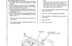
STRUT BAR 10 x 1.25 mm
39 N.m (3.9 kg-m, 28 Ib-ft)
EXPANSION TANK
CAP
: CORROSION RESISTANT BOLT (cont’dj
1. Move the seat bottoms and backs as far forward as
they will go.
2. Disconnect the battery negative terminal first, then
the positive terminal.
Loosen the drain plug from the radiator lower
tank.
Remove two drain bolts from the water pipes
Reinstall the drain bolts with new washers.
Loosen the front and rear engine drain bolts to
drain engine coolant from cylinder heads. Con-
nect rubber hoses to the drain bolts.
6. Drain transmission oil/fluid. Reinstall the drain plug
using a new washer.
CAUTION: Do not overtighten the drain plug.
7. Drain the engine oil. Reinstall the drain plug using a
new washer.
8. Lower the hoist.
9. Remove the strut bar.
CAUTION:
Use front and rear fender covers to avoid damaging
painted surfaces.
Unspecified items are common.
Unplug the wiring connectors carefully while holding
the coupler and the connector portion to avoid
damage.
Mark all wiring and hoses to avoid mis-connection.
Also, be sure that they do not contact other wiring or
hoses or interfere with other parts.
If the ground clearance needs to be increased, use a
scissors jack and install the rubber spacers to the coil
springs (page 1-8).
Put rubber pads under the jacking points when using
jacks or safety stands to avoid damaging the body
(page 1-9 to 11).
Engine Removal/Installation
(cont’d)
10. Disconnect the resistor connector and fan motor
connector, then remove the engine room fan
assembly.
ENGINE ROOM
FAN
ENGINE ROOM
FAN CONNECTOR
GROMMET
11. Remove the rear trim panels behind the
passenger’s seat, then disconnect four connectors
from Engine Control Module (ECM) and five con-
nectors from floor wire harness.
ENGINE WIRE
HARNESS CONNECTORS
ECM
PASSENGER’S
SEAT
FLOOR WIRE HARNESS
ENGINE WIRE
HARNESS
FUEL PUMP RESISTOR
CONNECTOR
GROUND
CABLE
6×1 .0 mm
10 N.m (1.0 kg-m, 7 Ib-ft)
CORROSION RESISTANT BOLT
6 x 1.0 mm
10 N.m d.Okg.m, 7 Ib-ft)
12. Remove the intake manifold plate and the top
cover.
13. Remove the throttle cable by loosening the locknut,
then slip the cable end out of the throttle bracket
and accelerator linkage.
INTAKE MANIFOLD
TOP COVER
6 x 1.0 mm
12 N.m (1.2 kg-m, 9 Ib-ft)
PLATE
ADJUSTING NUT
LOCKNUT
CABLE END
14. Relieve fuel pressure by slowly loosening the ser-
vice bolt on the fuel filter about one turn (see sec-
tion 11).
1 5. Remove the fuel feed pipe.
16. Remove the fuel return hose from the pressure con-
trol valve.
6 x 1.0 mm
22 N.m (2.2 kg-m. 16 Ib-ft) 12 N.m (1.2 kg-m, 9 Ib-ft)
FUEL FEED
PIPE
WASHERS
Replace.
FUEL RETURN
HOSE
17. Disconnect two hoses, then remove the expansion
tank.
6 x 1.0 mm
10 N.m (1.0 kg-m, 7 Ib-ft)
EXPANSION TANK
WATER HOSES
(cont’d)
Do not smoke while working on the
fuel system. Keep open flame away from work
area. Drain fuel only into an approved container.
CAUTION:
THROTTLE CABLE
NOTE:
Take care not to bend the cable when removing
it. Always replace a kinked cable with a new
one.
Adjust the throttle cable when installing (see
section 11).
Before disconnecting any fuel line, relieve the
fuel pressure as described above.
Place a shop towel over the fuel filter to prevent
pressurized fuel from spraying over the engine.
Engine Removal/Installation
(cont’d)
18. Remove the breather pipe, then remove the air in-
take duct and the air cleaner case.
6 x 1.0 mm
10 N.m (1.0kg-m, 7 Ib-ft) AIR CLEANER
CASE
BREATHER PIPE
19. Disconnect the evaporative emission (EVAP) con-
trol canister hose from throttle body.
20. Disconnect the brake booster vacuum hose from
the intake manifold.
EVAP CONTROL CANISTER
EVAP CONTROL
CANISTER
HOSE BRAKE BOOSTER
VACUUM HOSE
21. Disconnect the two engine wire harness connec-
tors from the side wire harness at left side of
engine compartment, and remove the engine wire
harness terminal and the starter cable terminal
from the main fuse box and clamps.
22. Remove the ground cable from the transmission.
MAIN FUSE BOX
6 x 1 . 0 mm
10 N.m (1.0 kg-m,
7 Ib-ft)ENGINE WIRE
HARNESS
23. Remove the water hoses and the heater hose from
the water passage.
HEATER HOSE
WATER HOSES
: CORROSION RESISTANT BOLT
24. Disconnect the three connectors from the emission
control box.
6 x 1.0 mm
10 N.m (1.0 kg-m,
7 Ib-ft)
EMISSION CONTROL
BOX
CONNECTORS
25. Move the trunk carpet and disconnect the right rear
sensor connector. Push the wire and connector
through the body hole into the engine compart-
ment.
26. Remove the front engine mounting bolt (page
5-29).
RIGHT REAR SENSOR
CONNECTOR
27. Raise hoist to full height.
28. Remove the clutch slave cylinder from the
transmission case (M/T see section 12).
CONTROL LEVER
SHIFT CABLE
CABLE COVER
CENTER ROD
ASSEMBLY
8×1 .25 mm
22 N.m (2.2 kg-m,
16 Ib-ft)
6 x 1 . 0 mm
8 N.m (0.8 kg-m, 6 Ib-ft)
6 x 1 . 0 mm
12 N.m (1.2 kg-m. 9 Ib-ft)
UNDER GUARD
10 x 1.25 mm
60 N.m (6.0 kg-m, 43 Ib-ft)
(cont’d): CORROSION RESISTANT BOLT/NUT
Do not disconnect the vacuum hoses.
Do not disconnect the clutch hose.
29. Remove the lower cover, then remove the shift
cable and select cable with cable bracket (M/T see
section 13).
30. Remove the cover, then remove the shift cable
(A/T see section 14).
NOTE:
Take care not to bend the cable when removing
it. Always replace a kinked cable with a new
one.
Adjust the cables when installing.
31. Remove the engine under guard and the center rod
assembly.
A/T:
Engine Removal/Installation
(cont’d )
32. Remove the rear beam rod assembly.
33. Remove the front beam. Lower and suspend the air
conditioning (A/C) compressor. Reinstall the front
beam.
NOTE:
PARKING BRAKE CABLE
Hang with
wire or rope.
FRONT BEAM
REAR BEAM
ROD ASSEMBLY
Remove.
A/C COMPRESSOR
Do not remove the compressor hoses.
Hang the A/C compressor with wire
or rope as shown.
Do not let it hang from hoses.
Retorque the two nuts
NOTE:
Do not remove the compressor hoses.
Do not let the compressor hang from hoses.
34. Remove the left and right parking brake cables.
35. Disconnect the stabilizer bar end links from the
knuckles, remove the bar. Separate the dampers
from the knuckles.
36. Remove the rear brake hoses. Plug the brake pipes
with rubber caps.
37. Remove the wheel sensor wire clamps.
NOTE: Perform steps 38 and 39 only if the
engine/transaxle assembly is to be removed from
the subframe.
38. Remove the adjust bolt and flange bolt, then
separate the lower control arm from the subframe.
39. Remove the flange bolt, then separate the toe con-
trol arm from the subframe.
CAUTION: Make sure that the reference marks on
the control arm are aligned.
: CORROSION RESISTANT
BOLT/NUT
6 x 1.0 mm
10 N.m (1.0 kg-m, 7 Ib-ft)
DAMPER
STABILIZER
Plug the brake
pipes with
rubber caps.
FLANGE BOLT
12 x 1.25 mm
95 N.m (9.5 kg-m, 69 Ib-ft)
12 x 1.25 mm
SELF-LOCKING NUT
Replace
85 N.m (8.5 kg-m, 62 Ib-ft)
WHEEL SENSOR
WIRE CLAMP
SELF-LOCKING NUT
14 x 1.5 mm
Replace
125 N.m (12.5 kg-m. 90 Ib-ft)
12 x 1.25 mm
SELF-LOCKING NUT
Replace
95 N.m (9.5 kg-m, 69 Ib-ft)
DAMPER
6 x 1.0 mm
10 N.m (1.0 kq-m, 7 Ib-ft)
STABILIZER 6 x 1.0 mm
10 N.m (1.0 kg-m, 7 Ib-ft)
FLANGE BOLT
12 x 1.25 mm
95 N·m (9.5 kg-m,
69 Ib-ft)
12 x 1.25 mm
SELF-LOCKING NUT
Replace
85 N·m (8.5 kg-m, 62 Ib-ft)
WHEEL SENSOR
WIRE CLAMP
SELF-LOCKING NUT
14 x 1.5 mm
Replace
125 N.m (12.5 kg-m, 90 Ib-ft) (cont’d)
12 x 1.25 mm
SELF-LOCKING NUT
Replace
95 N.m (9.5 kg-m, 69 Ib-ft)
Engine Removal/Installation
(cont’d)
40. Remove the heated oxygen sensor (HO2S)
connectors.
41. Remove the self-locking nuts, then remove front
exhaust pipe and the front three way catalytic
converter.
42. Remove the self-locking nuts, then separate the
rear three way catalytic converter from rear ex-
haust pipe and the muffler.
CAUTION: Do not use an air wrench or hammer to
remove or install the exhaust system unless you
first remove the heated oxygen sensors.
NOTE: Use new gaskets and self-locking nuts
when reassembling.
NOTE: Perform steps 43 and 44 only if the
engine/transaxle assembly is to be removed from
the subframe.
SELF-LOCKING NUTS
10 x 1.25 mm
34 N.m (3.4 kg-m.
25 Ib-ft)
REAR THREE WAY
CATALYTIC
CONVERTER
GASKETS
Replace.
FRONT
EXHAUST PIPE
SELF-LOCKING NUT
10 x 1.25 mm
55 N.m (5.5 kg-m,
40 Ib-ft) DRIVESHAFT
SET RING
Replace.
6 x 1.0 mm
10 N.m (1.0 kg-m, 7 Ib-ft)
HALF SHAFT
HEAT COVER
43. Remove the half shaft heat cover.
44. Remove the driveshafts.
NOTE:
Coat all precision finished surfaces with clean
engine oil or grease.
Tie plastic bags over the driveshaft ends.
45. Install the front engine mounting bolt, torque the
nut temporarily.
46. Position the Engine Removal/Installation Fixture
(07MAK –PR7020A) under the car. Lower the car
just above the fixture. With the help of an assis-
tant, attach the fixture to the subframe with two
12 mm nuts and two 10 mm bolts.
47. Adjust the pads on the fixture to support the oil
pan and transmission housing.
48. Lower the car so the fixture is resting on its casters
(or appropriate platform).
BODY SUPPORT
BRACKET
SIDE ENGINE
MOUNT
TRANSMISSION MOUNTING
BOLT
LOOSELY INSTALL
TWO 12 mm NUTS
ON STUDS HERE
LOOSELY
INSTALL
ONE 10 mm
BOLT HERE
ENGINE REMOVAL/INSTALLATION
FIXTURE
07MAK–PR7020A (cont’d)
Engine Removal/Installation
(cont’d)
49. Remove the two bolts from the side engine mount
near the alternator. Pivot the mounting bracket into
the housing of the body.
50. Remove the transmission mounting bolt.
51. Remove the twelve subframe-to-body mounting
bolts.
52. Raise the car a few inches.
53. Check that all wires and hoses are disconnected
from the engine assembly.
54. Raise the car completely off the engine/suspension
assembly. Roll the assembly from under the car.
TRUCK
GUIDE HOLE
(BODY)
TAPERED PUNCHGUIDE HOLE
(SIDE BEAM)
NOTE: When installing, align the bolt holes of the
beam brackets and body with a tapered punch.
55. Attach a chain hoist to the engine. Remove the
front and rear mounting bolts, then separate the
engine from the suspension and the beam
assembly.
CAUTION: Do not hit the engine oil cooler on the
rear right beam bracket.
FRONT ENGINE
MOUNT
REAR ENGINE
MOUNT
56. Install the engine in the reverse order of removal:
NOTE:
Combine the front beam and the rear beam rod
assembly, then torque the four mounting bolts.
Check that the set ring on the end of each
driveshaft clicks into place.
CAUTION: Use new set rings.
(cont’d)
Align the bolt holes of the beam brackets and
body with a tapered punch (page 5-28).
Temporarily torque the two front beam nuts and
front engine mounting bolt when installing the
A/C compressor.