Idle Control System
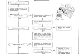
Troubleshooting Flowchart M/T Neutral Switch Signal
This signals the PGM-FI ECU when the transmission is in Neutral.
Inspection of M/T neutral Switch
Signal
Connect the ECU test harness
between the ECU and connector
(page 11-21).
0V
10V
B7
A26
Turn the ignition switch ON.
Measure voltage between B7 (+)
terminal and A26 (-) terminal in
Neutral position.
Is there voltage? Disconnect the 3P connector on
the M/T neutral switch.
LT GRN BLK
Connect LT GRN terminal to BLK
terminal.
Is there voltage?Shift transmission in gear. Replace M/T neutralswitch.
Repair open in LT GRIM wire be-
tween ECU (B7) and M/T neutral
pressure switch or BLK wire be-
tween M/T neutral switch and
G101.
Is there approx. 10 V?
Disconnect “B” connector from
engine wire harness only, not the
ECU.
Is there approx. 10 V?
M/T neutral switch signal is OK.
Substitute a known-
good ECU and re-
check.
If prescribed voltage is
now available, replace
the original ECU.
Reconnect “B” connector to
main wire harness and discon-
nect 3P connector on the M/T
neutral switch.
Is there approx. 10 V?
Repair short in LT GRN
wire between ECU
(B7) and the M/T
neutral switch.
Replace M/T neutral switch.