Category: Fuel & Emissions
Categories
nsxe11008a.pdf
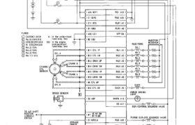
System Description Electrical Connections Main Menu Table of Contents System Description Electrical Connections MAIN RELAY FUEL PUMP RESISTOR SWITCH ® m IGNITION (D © I` v A (D ∙ J J\ I` A25 IGP] ∙ ≺∶↿ IGPZ PGZ A24 ∙ ∁↿↿ STS FLRI A1 ∙ ⊽ ELR: Aa ∙ FUSES ∙ A26 La1 ∙ −−− […]
Categories
nsxe11097a.pdf
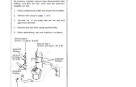
Fuel Filter Replacement Do not smoke while working on fuel system. Keep open flame away from work area. The filter should be replaced: every 4 years or 60,000 miles (96,000 km), whichever comes first or whenever the fuel pressure drops below the specified value (323–363 kPa,3.30–3.70 kg/cm2,46–53 psi with the pressure regulator vacuum hose disconnected) […]
Categories
nsxb11123a.pdf
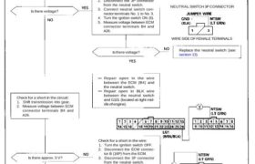
Neutral Switch Signal (M/T) This signals the ECM when the transmission is in neutral. Inspection of neutral switch signal. Check for an open in the circuit: 1. Turn the ignition switch ON (II). 2. Measure voltage between ECM connector terminals B4 and A26. Is there voltage? Check for a short in the circuit: 1. Shift […]
Categories
nsxe11003a.pdf

Component Locations Index FRONT KNOCK SENSOR Troubleshooting, page 11-62 COOLANT TEMPERATURE (TW) SENSOR Troubleshooting, page 11 – 48 EGR VALVE Troubleshooting, page 11-128 FUEL PUMP RESISTOR Inspection, page 11-106 CRANK/CYL SENSOR Troubleshooting, page 11-46 CONTROL BOX page 11-6 THROTTLE ANGLE SENSOR Troubleshooting, page 11-50 FAST IDLE VALVE Inspection, page 11-83 EACV Troubleshooting, page 11-70 INJECTOR […]
Categories
nsxd11098a.pdf
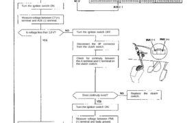
Idle Control System Troubleshooting Flowchart Clutch Switch Signal (M/T) This signals the ECM when the clutch is engaged. Inspection of clutch switch signal. Connect the test harness be- tween the ECM and connectors (see page 11-37). Turn the ignition switch ON. Measure voltage between C7 (+) terminal and A26 (-) terminal. Is voltage less than […]
Categories
nsxb11154a.pdf
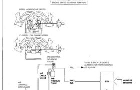
Intake Air System Intake Air Bypass (IAB) Control System Description Satisfactory power performance is achieved by closing and opening the intake air bypass (IAB) control valves. High torque at low engine speed is achieved when the valves are closed, whereas high power at high engine speed is achieved when the valves are opened. INTAKE AIR […]
Categories
nsxd11100a.pdf
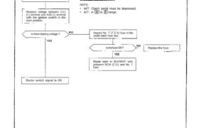
Idle Control System Troubleshooting Flowchart This signals the ECM when the engine is cranking. Inspection of starter switch signal. Connect the test harness be- tween the ECM and connectors (see page 11-37). Measure voltage between C11 (+) terminal and A26 (-) terminal with the ignition switch in the start position. Is there battery voltage ? […]
Categories
nsxd11135a.pdf
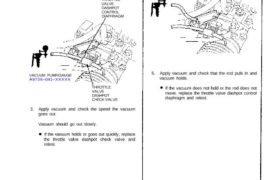
Testing 1. Check the vacuum line for leaks, blockage or a disconnected hose. 2. Disconnect the vacuum hose from the throttle valve dashpot control diaphragm, and connect a vacuum pump to the hose. THROTTLE VALVE DASHPOT CONTROL DIAPHRAGM 4. Connect a vacuum pump to the throttle valve dashpot control diaphragm. 5. Apply vacuum and check […]
Categories
nsxe11095a.pdf
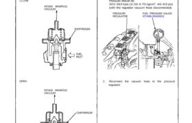
Pressure Regulator Description The fuel pressure regulator maintains a constant fuel pressure to the injectors. When the difference between the fuel pressure and manifold pressure exceeds 3.5 kg/cm2 (50 psi), the diaphragm is pushed upward, and the excess fuel is fed back into the fuel tank through the return line. CLOSE Testing Do not smoke […]
Categories
nsxe11072a.pdf
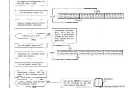
Idle Control System Troubleshooting Flowchart Air Conditioning Signal This signals the PGM-FI ECU when there is a demand for cooling from the air conditioning system. Inspection of Air Condition- ing Signal. Connect the ECU test harness between the ECU and connector. Disconnect “C” connector from the engine wire harness only, not the ECU (page 11-21). […]