Categories
Electrical

nsxb23296a.pdf

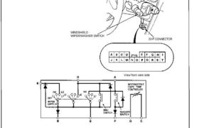
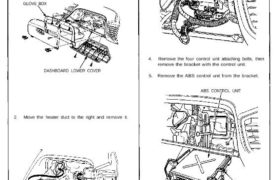
Wipers/Washers Windshield Wiper/Washer Switch Test 1. Remove the dashboard lower cover (see page 23-294). 2. Disconnect the 20-P connector from the floor wire harness. 3. Check for continuity between the terminals in each switch position according to the table. WINDSHIELD WIPER/WASHER SWITCH 20-P CONNECTOR View from wire side Attachments nsxb23296a (45 kB)

Categories
Manual Transmission

nsxb13019a.pdf

Change Holder Assembly Disassembly/Reassembly NOTE: Make sure the return springs are installed properly. Prior to reassembling, clean all parts in solvent, dry them, and apply lubricant to any contact surfaces. SHIFT PIECE LOCK COLLAR SHIFT PIECE SHAFT INTERLOCK CHANGE HOLDER SELECT RETURN SPRING 5TH/REVERSE RETURN SPRING 3 x 16 mm SPRING PIN Replace. Attachments nsxb13019a […]

Categories
Fuel & Emissions

nsxd11098a.pdf

Idle Control System Troubleshooting Flowchart Clutch Switch Signal (M/T) This signals the ECM when the clutch is engaged. Inspection of clutch switch signal. Connect the test harness be- tween the ECM and connectors (see page 11-37). Turn the ignition switch ON. Measure voltage between C7 (+) terminal and A26 (-) terminal. Is voltage less than […]

Categories
Differential

nsxb15007a.pdf

Reassembly NOTE: • If the limited slip differential clutch set was replaced, the 65 mm shim (differential housing cover side) and 112 mm shim (differential housing cover side) must be adjusted. • Reassemble the parts in the same order and direction they were before disassembly. • Lubricate the clutch disc surface with transmission oil. 1. […]

Categories
Cylinder Head & Valve Train

nsxd06023a.pdf

13. Remove the breather hose, and the air cleaner case (page 5-22). (cont’d) WATER HOSES Do not disconnect. EXPANSION TANK 12. Remove the expansion tank. NOTE: Do not disconnect water hoses. 6x 1.0 mm 10N.m (1.0kg-m, 7 Ib-ft) IGNITION COIL CONNECTOR 6 x 1.0 mm 12N.m (1.2kg-m, 9 Ib-ft) 6×1.0 mm 12 N.m (1.2 kg-m. […]

Categories
Brakes & ABS

nsxb19082a.pdf

TCS Control Unit Terminal Arrangement Main Menu Table of Contents TCS Control Unit Terminal Arrangement TCS CONTROL UNIT 14P CONNECTOR | 1 2 3 Q | 4 5 6 7 8 91011l121314 ‚Ир CONNECTOR WIRE SIDE OF FEMALE TERMINALS Voltage Terminal Wire Terminal sign . . „umher ook” (Termina name) Descr’pt’on Measurement Conditions Output terminals […]

Categories
Fuel & Emissions

nsxb11154a.pdf

Intake Air System Intake Air Bypass (IAB) Control System Description Satisfactory power performance is achieved by closing and opening the intake air bypass (IAB) control valves. High torque at low engine speed is achieved when the valves are closed, whereas high power at high engine speed is achieved when the valves are opened. INTAKE AIR […]

Categories
Body

nsxb20049a.pdf

Center Armrest Replacement CAUTION: When removing the center armrest inner panel, wrap the flat tip screwdriver with protective tape or a shop towel to prevent damage. NOTE: Take care not to scratch the center armrest, dashboard and rear center trim panel. Disassemble in numbered sequence. CENTER ARMREST INNER PANEL Open the Lid. INNER BOX Installation […]

Categories
Fuel & Emissions

nsxd11100a.pdf

Idle Control System Troubleshooting Flowchart This signals the ECM when the engine is cranking. Inspection of starter switch signal. Connect the test harness be- tween the ECM and connectors (see page 11-37). Measure voltage between C11 (+) terminal and A26 (-) terminal with the ignition switch in the start position. Is there battery voltage ? […]

Categories
Brakes & ABS

nsxb19070a.pdf

ABS Control Unit Replacement SRS components are located in this area. Review the SRS component locations, precautions, and procedures in the SRS section 24 before performing repairs or service. 1. Remove the dashboard lower cover and glove box, and disconnect the light connector. GLOVE BOX DASHBOARD LOWER COVER 2. Move the heater duct to the […]