Category: Manual Transmission
nsxb13038a.pdf
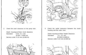
Oil Pump Clearance Inspection 1. Check the clearance between the transmission mating surface of the clutch housing and the oil pump gear. Standard: 0.3-0.8 mm (0.012-0.031 in) Service Limit: 0.9 mm (0.035 in) 2. Check the axial clearance on the pump rotor. Clutch Housing-to-Rotor Axial clearance Standard: 0.03—0.1 mm (0.001 – 0.004 in) Service Limit: […]
nsxb13019a.pdf
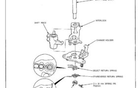
Change Holder Assembly Disassembly/Reassembly NOTE: Make sure the return springs are installed properly. Prior to reassembling, clean all parts in solvent, dry them, and apply lubricant to any contact surfaces. SHIFT PIECE LOCK COLLAR SHIFT PIECE SHAFT INTERLOCK CHANGE HOLDER SELECT RETURN SPRING 5TH/REVERSE RETURN SPRING 3 x 16 mm SPRING PIN Replace. Attachments nsxb13019a […]
nsxb13020a.pdf
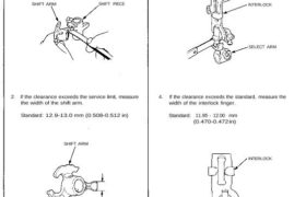
Change Holder Assembly, Shift Fork Clearance Inspection 1. Measure the clearance between the shift piece and shift arm. Standard: 0.05—0.25 mm (0.002-0.010 in) Service Limit: 0.5 mm (0.020 in) SHIFT ARM SHIFT PIECE 2. If the clearance exceeds the service limit, measure the width of the shift arm. Standard: 12.9-13.0 mm (0.508-0.512 in) SHIFT ARM […]
nsxb13030a.pdf
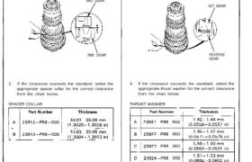
Countershaft Assembly Clearance Inspection 1. Measure the clearance between 2nd and 3rd gear. Standard: 0.04-0.10 mm (0.002-0.004 in) 3RD GEAR 2ND GEAR 2. If the clearance exceeds the standard, select the appropriate spacer collar for the correct clearance from the chart below. SPACER COLLAR 3. Measure the clearance between 1st and reverse gear. Standard: 0.04-0.10 […]
nsxb13004a.pdf
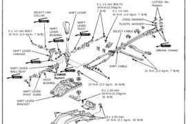
Gearshift Mechanism Overhaul NOTE: • Inspect rubber parts for wear and damage when disassembling. • Check that the new cotter pin is seated firmly. SELECT LINK COLLAR SHIFT LEVER 6 x 1.0 mm BOLTS 10 N-m (1.0 kg-m, 7 Ib-ft) 6 x 1.0 mm 10 N-m (1.0 kg-m, 7 Ib-ft) COTTER PIN Replace. 6 x […]
nsxb13035a.pdf
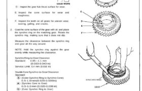
Synchro Ring, Gear Inspection 1. Inspect the synchro ring and gear. A : Inspect the inside of the synchro ring for wear. B : Inspect the synchro sleeve teeth and matching teeth on the synchro ring for wear (rounded off). C : Inspect the synchro sleeve teeth and matching teeth on the gear for wear […]
nsxb13026a.pdf
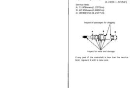
Mainshaft Assembly Inspection 1. Inspect the gear surface and bearing surface for wear and damage, then measure the mainshaft at points A, B, and C. Standard: A (Ball bearing surface): 32.002—32.018 mm (1.2599-1.2605 in) B (Needle bearing surface): 42.984—43.000 mm (1.6923-1.6929 in) C (Ball bearing surface): 30.984-31.000 mm (1.2198-1.2205 in) Service limit: A: 31.950 mm […]
nsxd13043a.pdf
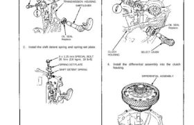
Transmission Reassembly 1. Install the oil seal, shift arm, and shift lever in the transmission housing. 8 x 1.0 mm SPECIAL BOLT 32 N.m (3.2 kg-m, 23 Ib-ft) SPRING WASHER SHIFT ARM TRANSMISSION HOUSING SHIFT LEVER OIL SEAL Replace. 2. Install the shift detent spring and spring set plate. 8 x 1.25 mm SPECIAL BOLT […]
nsxb13025a.pdf
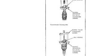
Disassembly 1. Remove the ball bearing using a bearing puller as shown. Clutch housing side: Transmission housing side: BEARING PULLER (Commercially available) BALL BEARING BEARING SEPARATOR, 0-4 1/2 in. (Commercially available) BEARING PULLER (Commercially available) BALL BEARING BEARING SEPARATOR, 0-4 1/2 in. (Commercially available) Mainshaft Assembly Disassembly CAUTION: Remove the synchro hubs using a press […]
nsxb13048a.pdf
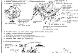
Transmission Assembly Installation NOTE: • Check that the two dowel pins are installed in the clutch housing. • Use only Super High Temp Urea Grease (P/N 08798-9002). 1. Place the transmission on the transmission jack, and raise it to the engine level. 2. Set the release fork to the clutch housing. 3. Install the two […]