(page 5-22).
(cont’d)
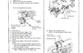
WATER HOSES
Do not disconnect.
EXPANSION TANK
12. Remove the expansion tank.
NOTE: Do not disconnect water hoses.
6x 1.0 mm
10N.m (1.0kg-m, 7 Ib-ft)
IGNITION COIL
CONNECTOR
6 x 1.0 mm
12N.m (1.2kg-m,
9 Ib-ft)
6×1.0 mm
12 N.m (1.2 kg-m. IGNITION COIL
CAUTION: Inspect the water pump when replacing the
timing belt (page 10-11).
O-RING
Replace.
8* 1.25 mm
8x 1.25 mm
22N.m (2.2 kg-m,
16 Ib-ft)
5. Lower the car.
6. Remove the strut bar (page 5-19).
7. Remove the intake manifold plate.
8. Remove the top cover (page 5-21).
9. Remove the ignition coil covers.
10. Remove the injector cover and the wire harness
covers.
11. Remove the ignition coils and the connecters.
22N.m (2.2 kg-m,
16 Ib-ft)
Replace.
Removal
9 Ib-ft)
HARNESS
COVERS
COVER
6x 1.0 mm
10N.m (1.0 kg-m,
7 Ib-ft)
FR
There are front and rear ignition coils and covers.
They can be identified by the mark FF (front) or
RR (rear) printed on them.
When installing front and rear ignition coil covers,
attach a rubber seal to the intake side.
NOTE:
Before removing the timing belt, mark direction of ro-
tation if it is to be reused.
NOTE:
1. Disconnect the negative terminal from the battery.
2. Raise the car.
3. Remove the right rear wheel/tire.
4. Remove the engine oil cooler base assembly.
Do not disconnect the hoses.
45N.m (4.5 kg-m. 33 Ib-ft)
14. Remove the connector, the terminal and the
alternator.
1 5. Remove the bolt from the side engine mount, then
push the side mounting bracket into the housing of
the body (page 5-27).
16. Remove the transmission mount.
17. Remove the cylinder head covers.
18. Turn the crankshaft so that the No. 1 piston is at
top dead center (page 6-25, 26).
19. Install a brace under the engine, then tilt the engine
approximately 5° using a jack.
Timing Belt
Removal (cont’d)
BELT COVER
ALTERNATOR
20. Remove the alternator bracket stiffener.
ALTERNATOR BRACKET
STIFFENER
21. Remove the air conditioning (A/C) compressor ad-
justing pulley and belt.
22. Remove the dipstick pipe mounting bolt, then re-
move the front and rear timing belt middle covers.
23. Remove the crankshaft pulley, then remove the tim-
ing belt lower cover.
24. Loosen the timing belt adjusting bolt 180° and
release the belt tension.
NOTE: Push the tensioner to release tension from
the belt, then retighten the adjusting bolt.
ADJUSTING BOLT
Do not remove. When
adjusting, loosen
it 180°.
25. Remove the timing belt from the pulleys.
CAUTION: Do not crimp or bend the timing belt more
than 90° or less than 25 mm (1 in.) in diameter.
DIAMETER
1.0 x 1.25 mm
45N.m (4.5 kg-m,
33 Ib-ft) 6 x 1.0 mm
12N.m (1.2 kg-m, 9 Ib-ft)
DIPSTICK PIPE
8×1.25 mm
22N.m
(2.2 kg-m,
16 Ib-ft)
9 Ib-ft)
6 x 1.0 mm
12N.m (1.2 kg-m.
6 Ib-ft29
ADJUSTING BOLT
8×1.25 mm
8N.m (0.8 kg-m,
1.0 x 1.25 mm
8×1.25 mm
12N.m (1.2 kg-m,
9 Ib-ft)