Main Menu
Table of Contents
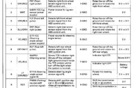
TCS Control Unit Terminal Arrangement
TCS CONTROL UNIT 14P CONNECTOR
| 1 2 3 Q | 4 5 6
7 8 91011l121314
‚Ир CONNECTOR WIRE SIDE OF FEMALE TERMINALS
Voltage
Terminal Wire Terminal sign . .
„umher ook” (Termina name) Descr’pt’on Measurement Conditions Output
terminals (Ignition Switch ON (lll) voltage
FRP (Front Detects right—front wheel Raise the car off the
‘l ORN/RED right pulse) sensor signal from the 1-GND ground and rotate the 0 V ↔ 5 V
ABS control unit right-front wheel.
GSEN VCC (Lg Power source for Lg sen’
Z WHT sensor power sor. 2-GND 5 V
7 SEEE‘XL
FLP (Front left Detects left‘front wheel Raise the car off the
3 ORN/BLK pulse) sensor signal from the 3—GND ground and rotate the 0 V ‹—› 5 \/
ABS control unit. left—front wheel.
RRP (Rear Detects right-rear wheel Raise the car off the
4 BLU/ORN right pulse) sensor signal from the 4-GND ground and rotate the 0 V ⇠≻ 5 V
ABS control unit. right-rear wheel.
STR VCC Power source for steering
5 VEL/RED (Steering angle sensor. 5_GND 5 ∀
angle sensor
power supply)
RLP (Rear left Detects left-rear wheel Raise the car off the
6 GRYNVHT pulse) sensor signal from the 6-GND ground and rotate the 0 V ≺→ 5 V
ABS control unit. IefHear wheel.
WARN1 Drives TCS indicator light Indicator light ON
(Warning lamp) (Shuts ofi the indicator Below 0.6 V
light ground circuit inside _
7 YEIJBLK the TCS control unit to 7 GND Indicator light OFF в
turn off the light when ¿Few
the system is normal). Vo ‘age
LT STR B (Steering Detects steering angle Rotate the steering
8 angle sensor sensor signal B. S-GND wheel. 5 V H O V
GRN/RED .
Signal B)
PNSW (Parking/ Detects shift position sig» Shift the transmission O V
neutral shift nal in [E] and E position. to P or N position.
9 RED ↼ ⊲ ⋅ ⋅ ⋅ ⋅ 9-GND . . .
position Signal) (Manual transmisswn. no Shift the ↥↾∂⊓⊴⊓⋅∎∎⋝≙∣∘⊓ to
conne‘mon) except IE or 圆 position. 10 V
STOP (Brake Detects brake switch sig- Brake pedal Battew
10 GRN/WHT switch signal) nal. 1o_GND depressed. voltage
Brake pedal released. O V
TCSW (TCS Detects TCS switch sig- Push the TCS switch. Battery
switch signal) nal. voltage
11 YEL/GRN 11—GND
Release the TCS
. 0 V
sw1tch.
LG1 (Logic Ground for the TCS con-
12 BRN/BLK ground) trol unit control circuits. 12’GND Bemw 0’3 V
LT STR A (Steering Detects steering angle Rotate the steering
13 GRN/wm, angle sensor sensor Signal A. ‘IS-GND wheel. 5V<—>0V
Signal A)
14 YEL lG‘l (lgnition Detects Ignition sWItch ”GND Battery
swnch) IG1 Signal. voltage
19-82
Mam Menu
Table of Contents
TCS CONTROL UNIT 20P CONNECTOR
T…
2 5 6 7 8 9 10
1 1 12 14 17 18 19
20P CONNECTOR WIRE SIDE OF FEMALE TERMINALS
Voltage
Terminal Wire Terminal sign Desai fion _ _
number color (Terminal name) p Measurement _ _ condmons output
terminals (Ignition Switch ON (ll)) voltage
PARK (Parking Detects Parking brake Pull the parking brake Below 0.6 V
brake swnch switch Signal. lever up.
2 GRN/RED si na.) 2—GND
g Release the parking Battery
brake lever. voltage
SDL SELD F| serial data line shield. Check for continuity. There is
5 BLK (Serial data 5—GND continu”
line shield) ⋎
− AT SHIFT (NT Detects А/Т shift position Shift the transmission A mx 4 V
6 ORN/BLU shift position) signal. B-GND to El position. pp ‘
. ⊲ ⋅ (5 V ‹—› 0 V)
Engine idling.
SCS (Service Detects service check SCS service connector 0 V
check signal) connector signal (diag— connected.
7 BLU nostic trouble code indi- 7’GND SCS sen,¡ce connector
canon)“ disconnected. 5 V
в BLK GSEN GND (Lg Ground for the Lg sensor. 8_GND Below 03 v
sensor ground)
GSEN SIG (Lg Detects Lg sensor signal. Connector side facing 3 5 ⋎
sensor signal) down. ‘
9 RED 9—GND Vertical 2.5 V
Connector Side facmg 1‘5 ∀
up.
1o WHT/YEL VB (Back-up Power source for diagnos» ↿∘≊≺⋮↾∖∥⊃ Elattery voltage at all Battery
voltage) tic trouble code memory. tlme. voltage
WARNZ Drives TCS indicator light Indicator light ON
(Warning (Shuts off the indicator Below 0’6 ∀
∏ YEL/BLK lamp) light ground clrcwt InSlde “_GND Indicator „ght OFF
the TCS control unit to Banery
turn off the light when voltage
the system is normal).
12 BRN/BLK “Gz ∥−∘⊊⇃∣∁ ∊↾∘⊔⋯⋅↿ f°r the ⊤≺⋅∶⊱ ∘⋅∘⊓− 12-GND Below 0.3 v
ground) trol unit control eircwts.
Fl SDL (Fl Serial data line to com- Engine idling.
м RED/BLU serial data line) municate with the ECM. ”’GND Аррюх’ 3 ∀
NEP (Engine Detects engine speed Engine idling. Approx. 6 V
17 GRN speed signal) signal. ”GND (12V‹-›0V)
STR GND Ground for the steering
18 BRN/WHT (Steering angle angle sensor. 18-GND Below 0.3 V
sensor ground)
GSEN SELD Lg sensor line shield. Check for continuity. There ¡s
19 BLK (Lg sensor 19-GND commun
shield) ⋎⋅
19-83