Engine Lubrication Special Tools 8−2. . . . . . . . . . . . . . . . . . . . . . . . . . . . . . . . . . . . . . . . . . . Component Location Index 8−3. . . . . […]
Categories
nsx08index.pdf
Engine Lubrication Special Tools 8−2. . . . . . . . . . . . . . . . . . . . . . . . . . . . . . . . . . . . . . . . . . . Component Location Index 8−3. . . . . […]
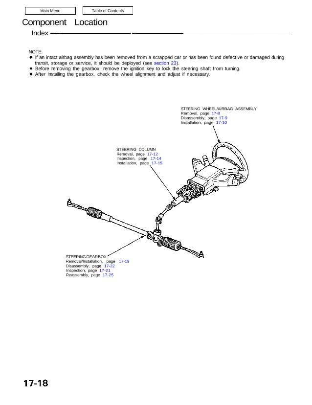
Component Location Index NOTE: If an intact airbag assembly has been removed from a scrapped car or has been found defective or damaged during transit, storage or service, it should be deployed (see section 23). Before removing the gearbox, remove the ignition key to lock the steering shaft from turning. After installing the gearbox, check […]
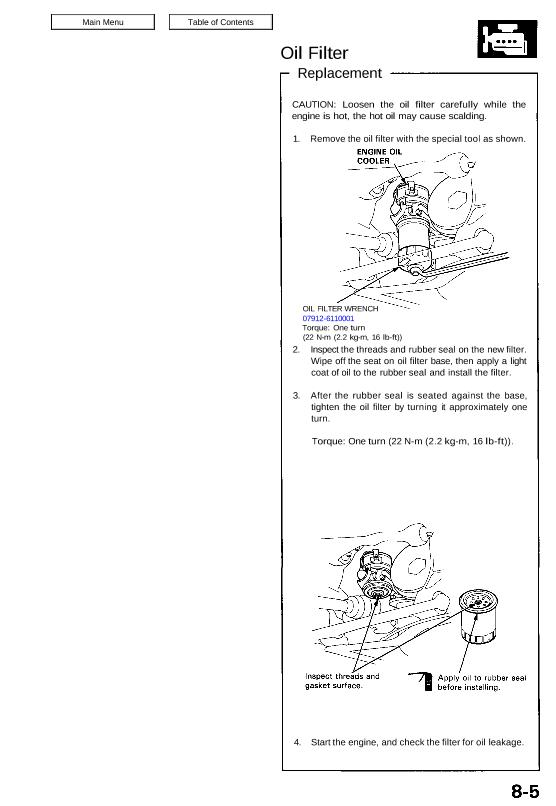
Oil Filter Replacement CAUTION: Loosen the oil filter carefully while the engine is hot, the hot oil may cause scalding. 1. Remove the oil filter with the special tool as shown. 2. Inspect the threads and rubber seal on the new filter. Wipe off the seat on oil filter base, then apply a light coat […]
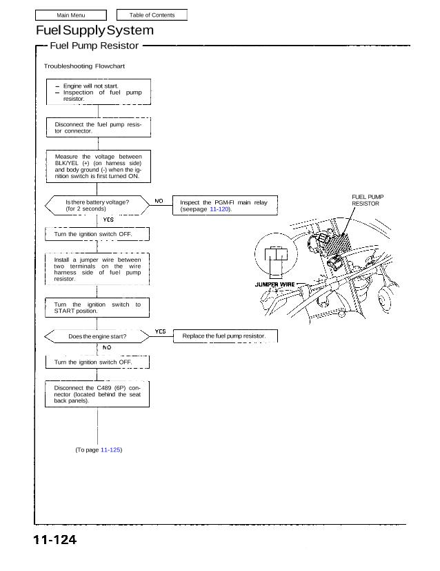
Fuel Supply System Fuel Pump Resistor Troubleshooting Flowchart (To page 11-125) FUEL PUMP RESISTORInspect the PGM-FI main relay (seepage 11-120). Engine will not start. Inspection of fuel pump resistor. Disconnect the fuel pump resis- tor connector. Measure the voltage between BLK/YEL (+) (on harness side) and body ground (-) when the ig- nition switch is […]
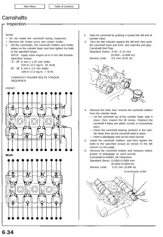
Camshafts Inspection NOTE: • Do not rotate the camshaft during inspection. • Remove the rocker arms and rocker shafts. 1. Put the camshafts, the camshaft holders and holder plates on the cylinder head, and then tighten the bolts to the specified torque. NOTE: Apply clean engine oil to 8 mm bolt threads. Specified torque: 8 […]
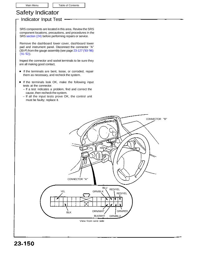
Safety Indicator Indicator Input Test SRS components are located in this area. Review the SRS component locations, precautions, and procedures in the SRS section (24) before performing repairs or service. Remove the dashboard lower cover, dashboard lower pad and instrument panel. Disconnect the connector “A” (30-P) from the gauge assembly (see page 23-127 (’93-’96) (’91-’92)). […]
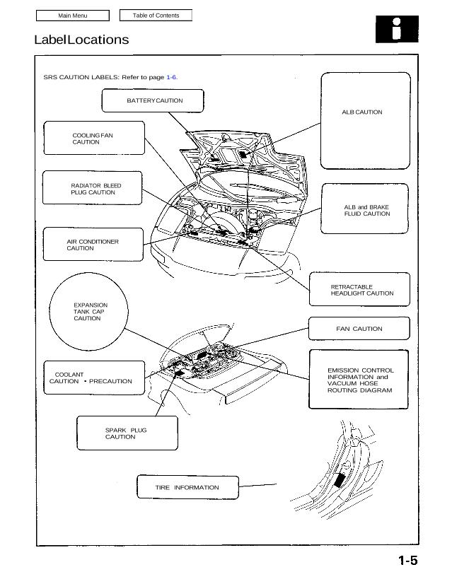
Label Locations SRS CAUTION LABELS: Refer to page 1-6. BATTERY CAUTION ALB CAUTION ALB and BRAKE FLUID CAUTION COOLING FAN CAUTION RADIATOR BLEED PLUG CAUTION AIR CONDITIONER CAUTION RETRACTABLE HEADLIGHT CAUTION FAN CAUTION EXPANSION TANK CAP CAUTION COOLANT CAUTION PRECAUTION EMISSION CONTROL INFORMATION and VACUUM HOSE ROUTING DIAGRAM SPARK PLUG CAUTION TIRE INFORMATION Warning/Caution Label […]
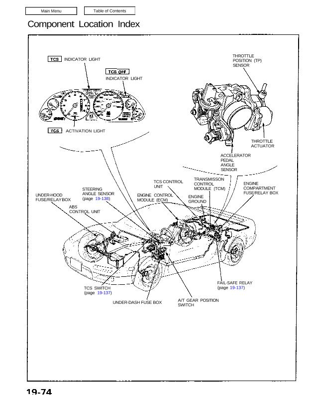
Component Location Index INDICATOR LIGHT ACTIVATION LIGHT INDICATOR LIGHT UNDER-HOOD FUSE/RELAY BOX ABS CONTROL UNIT STEERING ANGLE SENSOR (page 19-138) TCS SWITCH (page 19-137) UNDER-DASH FUSE BOX A/T GEAR POSITIONSWITCH FAIL-SAFE RELAY (page 19-137) ENGINE COMPARTMENT FUSE/RELAY BOX TRANSMISSON CONTROL MODULE (TCM) ENGINE GROUND TCS CONTROL UNIT ENGINE CONTROL MODULE (ECM) ACCELERATOR PEDAL ANGLE SENSOR […]
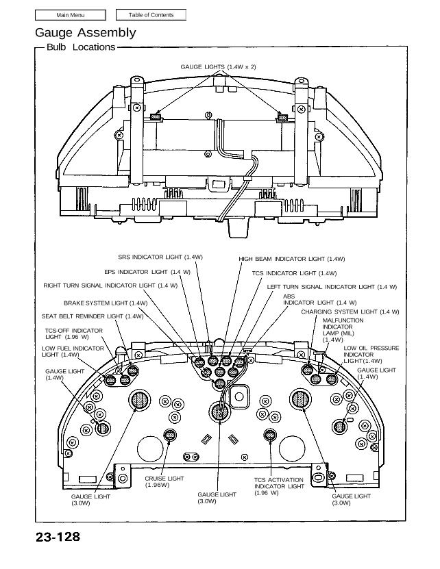
Gauge Assembly Bulb Locations SRS INDICATOR LIGHT (1.4W) EPS INDICATOR LIGHT (1.4 W) RIGHT TURN SIGNAL INDICATOR LIGHT (1.4 W) BRAKE SYSTEM LIGHT (1.4W) SEAT BELT REMINDER LIGHT (1.4W) TCS-OFF INDICATOR LIGHT (1.96 W) LOW FUEL INDICATOR LIGHT (1.4W) GAUGE LIGHT (1.4W) GAUGE LIGHT (3.0W) CRUISE LIGHT (1.96W) GAUGE LIGHT (3.0W) TCS ACTIVATION INDICATOR LIGHT […]
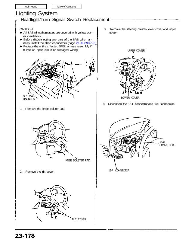
Lighting System Headlight/Turn Signal Switch Replacement CAUTION: All SRS wiring harnesses are covered with yellow out- er insulation. Before disconnecting any part of the SRS wire har- ness, install the short connectors (page 24-10(’93-’96)). Replace the entire affected SRS harness assembly If ft has an open circuit or damaged wiring. SRS MAIN HARNESS 1. Remove […]