Indicator Input Test
SRS components are located in this area. Review the SRS
component locations, precautions, and procedures in the
SRS section (24) before performing repairs or service.
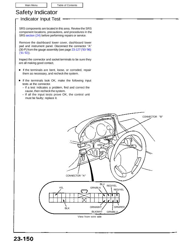
Remove the dashboard lower cover, dashboard lower
pad and instrument panel. Disconnect the connector “A”
(30-P) from the gauge assembly (see page 23-127 (’93-’96)
(’91-’92)).
Inspect the connector and socket terminals to be sure they
are all making good contact,
If the terminals are bent, loose, or corroded, repair
them as necessary, and recheck the system.
If the terminals look OK, make the following input
tests at the connector.
– If a test indicates a problem, find and correct the
cause, then recheck the system.
– If all the input tests prove OK, the control unit
must be faulty; replace it.
CONNECTOR “B”
CONNECTOR “A”
YEL GRN/BLK
BLU RED/YEL
RED/YEL
BLK ORN/WHT
BLK/WHT
GRN/RED
GRN/BLU
View from wire side
*1: Terminal is in floor wire harness side of connector. *2: NSX-T (open top) only
Main Menu Table of Contents
No. Wire Test condition Test: Desired result Possible cause if result is not obtained
Under all conditions Check for continuity to ground: – Poor ground (G401, G402, G403)
1 BLK . . . ‚
There should be continuity. – An open in the Wire
2 VEL Ignition switch ON (ll) Check for voltage to ground: – Blown No. 5 (15 A) fuse
There should be battery voltage. – An open in the wire
Brake pedal pushed Check for continuity to ground: – Blown No. 45 (20 А) fuse
There should be less than 4 k9 – Faulty brake switch
with the pedal pushed. – Blown brake light bulbs
3 ORN/WHT ∙ Faulty brake light failure sensors
∙ Poor ground (6551)
– An open in the ORNNVHT or
GRN/WHT wire
Engine compartment Check for continuity to ground: – Faulty engine compartment lid
a BLU lid open There should be continuity. switch
∙ Poor ground (G401, G402, G403)
– An open in the wire
Trunk lid open Check for continuity to ground: – Faulty trunk latch switch
⋮ GRN/ELK There should be continuity. ⋅ Poor ground (6551)
NOTE: Before testing, remove the ∙ ⋀⋂ open in the wire
No. 34 (15 A) fuse.
GRN/BLU Driver’s door Open Check for continuity to ground: ⋅ Faulty door switch
6 There should be continuity. – Poor ground (G401, G402, G403)
GRN RED Passenger’s door open NOTE: Before testing, remove the – An open in the wire.
’ No. 34 (15 A) fuse.
Ceiling light switch in Connect to ground: The ceiling – Blown No. 34 (15 A) fuse
MIDDLE position light should come on. ∙ Faulty ceiling light
7 BLK/WHT – An open in the WHT/BLU or
BLK/WHT wire
Retractable headlight *‘ Connect battery power to the – Faulty retractable headlight con-
RED/YEL sub—harness (left or BLU/RED terminal (right retractor) trol unit
8 right) disconnected or BLU terminal (left retractor); ∙ Seized, damaged, or improperly
RED/YEL‘ . .
after about four seconds there Installed retractor linkage
should be battery voltage.
Roof unlatched or off Check for continuity to ground: – Faulty roof holder switch
There should be continuity. – Faulty roof lock switches
9 – Poor ground (G401. G402, G403)
*2 RED/YEL2 – An open in the RED/YELz or
BLU/GRN wire
– An open in both the RED/GRN and
RED/YEL3 wires
*1: Terminal is in floor wire harness side of connector.
*2: NSX-T (open top) only
23-151