Categories
Automatic Transmission

nsxd14083a.pdf

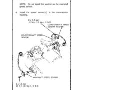
Mainshaft/Countershaft Speed Sensors Replacement 1. Remove the 6 mm bolt from the transmission hous- ing and remove the mainshaft and countershaft speed sensors. 2. Replace the O-ring with a new one before reassembling the mainshaft and countershaft speed sensors. 3. Install the washer on the countershaft speed sensor. NOTE: Do not install the washer on […]

Categories
Automatic Transmission

nsxd14002a.pdf

Ref. No. Tool Number Description Must be used with commercially available 3/8 in. x16 threads/in. slide hammer. Special Tools Page Reference 14-107 14-135, 138 14-135, 138 14-135, 138 14-51, 88 14-92 14-92 14-92 14-92 14-143 14-141, 143 14-141, 142, 143 14-141, 142, 143 14-106, 149 14-142 07HAC-PK4010A 07GAE-PG40200 07HAE-PL50100 07LAE-PX40100 07LAJ-PT3010A 07MAJ-PY4011A 07MAJ-PY40120 07406-0020400 07406-0070300 […]

Categories
Electrical

nsxb23161a.pdf

A/T Gear Position Switch Replacement SRS components are located in this area. Review the SRS component locations, precautions, and procedures in the SRS section (24) before performing repairs or ser- vice. 1. Remove the console, then disconnect the 12-P and 2-P connectors from the A/T gear position switch. SWITCH SLIDER (In ) PIN A/T GEAR […]

Categories
Manual Transmission

nsxb13033a.pdf

Reassembly CAUTION: • Prior to reassembling, clean all the parts in solvent, dry them, and apply lubricant to any contact parts. • Press the 3rd, 4th and 5th gears on the countershaft without lubrication. • When installing the 3rd, 4th and 5th gears, support the shaft on steel blocks, and install the gears using a […]

Categories
Cylinder Head & Valve Train

nsxd06041a.pdf

Intake Valve Dimensions A Standard (New): 34.9 — 35.1 mm (1.374-1.382 in) B Standard (New): 111.05-111.40 mm (4.372-4.386 in) C Standard (New): 5.475—5.485 mm (0.2156-0.2159 in) C Service Limit: 5.445 mm (0.2144 in) D Standard (New): 1.05—1.35 mm (0.041-0.053 in) D Service Limit: 0.85 mm (0.033 in) Exhaust Valve Dimensions A Standard (New): 29.9—30.1 mm […]

Categories
Electrical

nsxb23078a.pdf

Starting System Starter Test NOTE: The air temperature must be between 59 and 100°F (15 and 38°C) before testing. Recommended Procedure: • Use a starter system tester. • Connect and operate the equipment in accor- dance with manufacturer’s instructions. Alternate Procedure: • Use the following equipment: – Ammeter, 0-400 A – Voltmeter, 0-20 V (accurate […]

Categories
Fuel & Emissions

nsxb11062a.pdf

PGM-FI System Engine Control Module (ECM) The Malfunction Indicator Lamp (MIL) stays on or comes on after two seconds. Check the Diagnostic Trouble Code (DTC): 1. Connect a scan tool or Honda PGM Tester. 2. Turn the ignition switch ON (II). 3. Read the DTC with the scan tool or Honda PGM Tester. NOTE: • […]

Categories
Steering

nsxd17051a.pdf

Troubleshooting Chart The EPS has been reported on: Connect the service check connector with a jumper wire (see page 17-43). Turn on the ignition switch. Read the Diagnostic Trouble Code (DTC) and perform the troubleshooting according to the troubleshooting chart below. 17-52 17-54 17-56 17-59 17-60 17-62 Attachments nsxd17051a (87 kB)

Categories
Cylinder Head & Valve Train

nsxb06006a.pdf

VTEC VTEC Solenoid Valve Inspection 1. Disconnect the 2P connector from the VTEC sole- noid valve. 2. Measure resistance between the BLU/YEL (front/rear) terminals and body ground. Resistance: approx 14 – 30 ohms BLU/YEL 3. If the resistance is within specifications, remove the VTEC solenoid valve from the cylinder head, and check the VTEC solenoid […]

Categories
Brakes & ABS

nsxb19068a.pdf

Accumulator/Pressure Switch Accumulator/Pressure Switch Removal 1. Drain the high pressure brake fluid from the power unit (see page 19-62). 2. Remove three 6 mm flange bolts, then remove the accumulator from the pressure switch joint. 6 x 1.0 mm 10 N-m (1.0 kg-m, 7 Ib-ft) PRESSURE SWITCH JOINT ACCUMULATOR Accumulator Disposal The accumulator contains high-pressure […]