A/T Gear Position Switch
Replacement
SRS components are located in this area. Review the
SRS component locations, precautions, and procedures
in the SRS section (24) before performing repairs or ser-
vice.
1. Remove the console, then disconnect the 12-P and
2-P connectors from the A/T gear position switch.
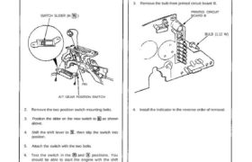
SWITCH SLIDER (In )
PIN
A/T GEAR POSITION SWITCH
2. Remove the two position switch mounting bolts.
3. Position the slider on the new switch to as shown
above.
4. Shift the shift lever to , then slip the switch into
position,
5. Attach the switch with the two bolts.
6. Test the switch in the and positions. You
should be able to start the engine with the shift
lever in position anywhere in the range of free
play.
7. Connect the 12-P and 2-P connectors, clamp the
harness, and install the console.
Bulb Replacement
SRS components are located in this area. Review the
SRS component locations, precautions, and procedures
in the SRS section (24) before performing repairs or ser-
vice.
1. Remove the gauge assembly (see page 23-126).
2. Disassemble the gauge assembly (see page 23-129
(’93-’96) (’91-’92)).
3. Remove the bulb from printed circuit board B.
PRINTED CIRCUIT
BOARD B
BULB (1.12 W)
4. Install the indicator in the reverse order of removal.
Replacement
SRS components are located in this area. Review the
SRS component locations, precautions, and procedures
in the SRS section (24) before performing repairs or ser-
vice.
1. Remove the console, then disconnect the 12-P and
2-P connectors from the A/T gear position switch.
SWITCH SLIDER (In )
PIN
A/T GEAR POSITION SWITCH
2. Remove the two position switch mounting bolts.
3. Position the slider on the new switch to as shown
above.
4. Shift the shift lever to , then slip the switch into
position,
5. Attach the switch with the two bolts.
6. Test the switch in the and positions. You
should be able to start the engine with the shift
lever in position anywhere in the range of free
play.
7. Connect the 12-P and 2-P connectors, clamp the
harness, and install the console.
Bulb Replacement
SRS components are located in this area. Review the
SRS component locations, precautions, and procedures
in the SRS section (24) before performing repairs or ser-
vice.
1. Remove the gauge assembly (see page 23-126).
2. Disassemble the gauge assembly (see page 23-129
(’93-’96) (’91-’92)).
3. Remove the bulb from printed circuit board B.
PRINTED CIRCUIT
BOARD B
BULB (1.12 W)
4. Install the indicator in the reverse order of removal.