Categories
Electrical

nsxb23203a.pdf

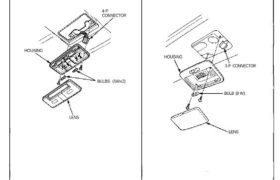
Ceiling Light Replacement Coupe: 1. Turn the light switch OFF. 2. Pry off the lens. 3. Remove the two bolts and the housing. 4. Disconnect the 4-P connector from the housing. 4-P CONNECTOR HOUSING BULBS (5Wx2) LENS NSX-T (open top): 1. Turn the light switch OFF. 2. Pry off the lens. 3. Remove the two […]

Categories
Automatic Transmission

nsxd14160a.pdf

INDEX MARK SHIFT INDICATOR PANEL SRS MAIN HARNESS 1. Check that the index mark of the indicator aligns with the N mark of the shift indicator panel with the trans- mission in NEUTRAL. 2. If not aligned, remove the cellnter console panel (see section 20). 3. Remove the shift indicator panel mounting screws and adjust […]

Categories
Manual Transmission

nsxb13031a.pdf

Disassembly 1. Securely clamp the countershaft assembly in a bench vise with wood blocks. 2. Raise the locknut tab from the groove of the countershaft, and remove the locknut and the spring washer. NOTE: The locknut has left-hand threads. WOOD BLOCKS 3. Remove the ball bearing using a bearing puller as shown. BEARING PULLER (Commercially […]

Categories
Intake Manifold & Exhaust System

nsxd09002a.pdf

Intake Manifold Illustrated Index NOTE: Use new O-ring, gaskets and self-locking nuts. INSTALL PIPE 6 x 1.0 mm12 N.m (1.2 kg-m, 9 Ib-ft) 6 x 1.0 mm 12 N.m (1.2 kg-m, 9 Ib-ft) IGNITION CONTROL MODULE (ICM) 5 x 10 mm 6 N·m (0.6 kg-m, 4 Ib-ft) INTAKE AIR TEMPERATURE (IAT) SENSOR 6 x 1.0 […]

Categories
Maintenance

nsxa04006a.pdf

Follow the Severe Conditions Maintenance Schedule if the car is driven MAINLY under one or more of the Severe Driving Conditions (pages 4 – 7 ) 8-4, 8-5 11-149 6-9 23-96 6-15, 10-11 23-109 11-128 10-6 13-2a 14-105 19-6, 19-9 19-17, 19-19 19-4 *1: Refer to Base Service Manual (’95 NSX, P/N 61SL004) *2: Measured […]

Categories
Fuel & Emissions

nsxd11110a.pdf

Fuel Supply System Fuel Injectors (cont’d) Replacement Do not smoke during the work. Keep open flames away from your work area. 1. Relieve fuel pressure (see page 11-105). 2. Remove the intake manifold covers. 3. Disconnect the connectors from the fuel injectors and the IAT sensor. 4. Disconnect the vacuum hose and fuel return hose […]

Categories
Fuel & Emissions

nsxd11003a.pdf

Component Locations Index ENGINE COOLANT TEMPERATURE (ECT) SENSOR Troubleshooting, page 11 -66 INTAKE AIR TEMPERATURE (IAT) SENSOR Troubleshooting, page 11-70 FUEL PUMP RESISTER Troubleshooting, page 11-124 CRANKSHAFT POSITION/ CYLINDER POSITION (CKP/CYP) SENSOR Troubleshooting, page 11-64 FUEL INJECTOR RESISTER Testing, page 11-112 FRONT HEATED OXYGEN SENSOR (HO2S) Troubleshooting, page 11-48 REAR KNOCK SENSOR (KS) Troubleshooting, page […]

Categories
Cylinder Head & Valve Train

nsxd06038a.pdf

Camshafts Inspection 1. Put the camshafts, the camshaft holders and holder pipes on the cylinder head, and then tighten the bolts to the specified torque. NOTE: Apply clean engine oil to 8 mm bolt threads. Specified torque: 8 mm x 1.25 mm bolts: 22N.m (2.2 kg-m, 16 Ib-ft) 6 mm x 1.0 mm bolts: 10N.m […]

Categories
Electrical

nsxd23012a.pdf

Relay and Control Unit Locations Engine Compartment REAR WINDOW DEFOGGER RELAY ENGINE COMPARTMENT FUSE/RELAY BOX ENGINE COMPARTMENT FAN RELAY Wire colors: YEL/BLU, BLK/YEL, WHT/RED, and WHT/BLU IGNITION CONTROL MODULE (ICM) Attachments nsxd23012a (160 kB)

Categories
Engine Block

nsxb07014a.pdf

Connecting Rods Selection Each rod is sorted into one of four tolerance ranges (from 0 to 0.024 mm, in 0.006 mm increments) depen- ding on the size of its big end bore. It’s then stamped with a number (1, 2, 3 or 4) indicating that tolerance. You may find any combination of 1, 2, 3 […]