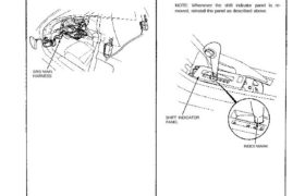
INDEX MARK
SHIFT INDICATOR
PANEL
SRS MAIN
HARNESS
1. Check that the index mark of the indicator aligns with
the N mark of the shift indicator panel with the trans-
mission in NEUTRAL.
2. If not aligned, remove the cellnter console panel (see
section 20).
3. Remove the shift indicator panel mounting screws and
adjust by moving the panel.
NOTE: Whenever the shift indicator panel is re-
moved, reinstall the panel as described above.
All SRS wiring harnesses are covered with yellow
outer insulation.
Before disconnecting any part of the SRS wire
harness, install the short connectors (see page
23-328).
Replace the entire affected SRS harness assembly if
it has an open circuit or damaged wiring.
CAUTION:
Adjustment
Shift Indicator Panel
