Categories
Manual Transmission

nsxb13020a.pdf

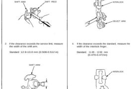
Change Holder Assembly, Shift Fork Clearance Inspection 1. Measure the clearance between the shift piece and shift arm. Standard: 0.05—0.25 mm (0.002-0.010 in) Service Limit: 0.5 mm (0.020 in) SHIFT ARM SHIFT PIECE 2. If the clearance exceeds the service limit, measure the width of the shift arm. Standard: 12.9-13.0 mm (0.508-0.512 in) SHIFT ARM […]

Categories
Body

nsxb20012a.pdf

Doors Moldings Removal NOTE: Lower the glass fully. Remove: (see pages 20-7(’93-’96),6(’91-’92), 8(’93-’96),7(’91-’92) Trim plate Sash covers Inside door handle Door panel Inner molding: NOTE: Pry the clips out using a flat tip screwdriver, then pull up the inner molding. INNER MOLDING CLIP INNER MOLDING Outer molding: NOTE: Remove the front sash panel (see page […]

Categories
Fuel & Emissions

nsxe11095a.pdf

Pressure Regulator Description The fuel pressure regulator maintains a constant fuel pressure to the injectors. When the difference between the fuel pressure and manifold pressure exceeds 3.5 kg/cm2 (50 psi), the diaphragm is pushed upward, and the excess fuel is fed back into the fuel tank through the return line. CLOSE Testing Do not smoke […]

Categories
Electrical

nsxb23253a.pdf

Main Switch Test 1. Remove the glove box, and disconnect the 2-P con- nector from the switch. 2. Check for continuity between the terminals. • There should be continuity between the No. 1 terminal and No. 2 terminal with the main switch ON. • There should be no continuity with the main switch OFF. View […]

Categories
Electrical

nsxe23209a.pdf

Cancel Unit Input Test Remove the steering column covers. Disconnect the 10-P connector from the cancel unit. Make the following input tests at the 10-P connector ter- minals. If all tests prove OK, but the turn signal lights fails to work, replace the cancel unit. CANCEL UNIT 10-P CONNECTOR TURN SIGNAL SWITCH C10(BLK) C8(BLU/GRN) C6(GRY) […]

Categories
Electrical

nsxe23286a.pdf

Cruise Control CAUTION: All SRS electrical wiring harnesses are covered with yellow outer insulation. Before disconnecting the SRS wire harness, install the short connector on the airbag (see page 23-323). Replace the entire affected SRS harness assembly if it has an open circuit or damaged wiring. SRS MAIN WIRE MARNESS MAIN SWITCH Test, page 23-295 […]

Categories
Automatic Transmission

nsxd14118a.pdf

O-RING Replace. 4TH ACCUMLATOR PISTON 1ST ACCUMULATOR PISTON O-RINGS Replace. DOWEL PIN THROTTLE SEPARATOR PLATE THROTTLE VALVE BODY THROTTLE VALVE BSERVO VALVE (SHIFT FORK SHAFT) 6 x 1.0 mm 12 N.m (1.2 kg-m, 9 Ib-ft) ATF MAGNET O-RING Replace. ATF STRAINER 6 x 1.0 mm 12 N.m (1.2 kg-m. 9 Ib-ft) ACCUMULATOR COVER 6 x […]

Categories
Fuel & Emissions

nsxe11072a.pdf

Idle Control System Troubleshooting Flowchart Air Conditioning Signal This signals the PGM-FI ECU when there is a demand for cooling from the air conditioning system. Inspection of Air Condition- ing Signal. Connect the ECU test harness between the ECU and connector. Disconnect “C” connector from the engine wire harness only, not the ECU (page 11-21). […]

Categories
Brakes & ABS

nsxb19015a.pdf

Pushrod Clearance Adjustment NOTE: Master cylinder pushrod-to-piston clearance must be checked and adjustments made, if necessary, before installing master cylinder. 1. Set the special tool on the master cylinder body; push in the center shaft until the top of it contacts with the end of the secondary piston by turning the adjusting nut. 07JAG-SD40100 2. […]

Categories
Steering

nsxd17010a.pdf

Steering Wheel Installation NOTE: Before installing the steering wheel, make sure the front wheels are straight ahead. CAUTION: Be sure to install the harness wires so that they are not pinched or interfering with other car parts. Do not replace the original steering wheel with any other design, since it will make it impossible to […]