Pushrod Clearance Adjustment
NOTE: Master cylinder pushrod-to-piston clearance
must be checked and adjustments made, if necessary,
before installing master cylinder.
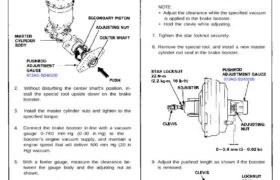
1. Set the special tool on the master cylinder body;
push in the center shaft until the top of it contacts
with the end of the secondary piston by turning the
adjusting nut.
07JAG-SD40100
2. Without disturbing the center shaft’s position, in-
stall the special tool upside down on the brake
booster.
3. Install the master cylinder nuts and tighten to the
specified torque.
4. Connect the brake booster in-line with a vacuum
gauge 0-760 mm Hg (0 -30 in Hg) to the
booster’s engine vacuum supply, and maintain a
engine speed that will deliver 500 mm Hg (20 in
Hg) vacuum.
5. With a feeler gauge, measure the clearance be-
tween the gauge body and the adjusting nut as
shown.
NOTE: If the clearance between the gauge body
and adjusting nut is 0.4 mm (0.02 in), the pushrod-
to-piston clearance is 0 mm. However, if the
clearance between the gauge body and adjusting
nut is O mm, the pushrod-to-piston clearance is 0.4
mm (0.02 in) or more. Therefore, it must be ad-
justed and rechecked.
6. If clearance is incorrect, loosen the star locknut and
turn the adjuster in or out to adjust.
NOTE:
• Adjust the clearance while the specified vacuum
is applied to the brake booster.
• Hold the clevis while adjusting.
7. Tighten the star locknut securely.
8. Remove the special tool, and install a new master
cylinder rod seal in the brake booster.
07JAG-SD40100
9. Adjust the pushrod length as shown if the booster
is removed.
10. Install the master cylinder (see page 19-12).
11. After installation, perform the following inspec-
tions and adjust if necessary.
• Brake pedal height (see page 19-4).
• Brake pedal free play (see page 19-4).
NOTE: Master cylinder pushrod-to-piston clearance
must be checked and adjustments made, if necessary,
before installing master cylinder.
1. Set the special tool on the master cylinder body;
push in the center shaft until the top of it contacts
with the end of the secondary piston by turning the
adjusting nut.
07JAG-SD40100
2. Without disturbing the center shaft’s position, in-
stall the special tool upside down on the brake
booster.
3. Install the master cylinder nuts and tighten to the
specified torque.
4. Connect the brake booster in-line with a vacuum
gauge 0-760 mm Hg (0 -30 in Hg) to the
booster’s engine vacuum supply, and maintain a
engine speed that will deliver 500 mm Hg (20 in
Hg) vacuum.
5. With a feeler gauge, measure the clearance be-
tween the gauge body and the adjusting nut as
shown.
NOTE: If the clearance between the gauge body
and adjusting nut is 0.4 mm (0.02 in), the pushrod-
to-piston clearance is 0 mm. However, if the
clearance between the gauge body and adjusting
nut is O mm, the pushrod-to-piston clearance is 0.4
mm (0.02 in) or more. Therefore, it must be ad-
justed and rechecked.
6. If clearance is incorrect, loosen the star locknut and
turn the adjuster in or out to adjust.
NOTE:
• Adjust the clearance while the specified vacuum
is applied to the brake booster.
• Hold the clevis while adjusting.
7. Tighten the star locknut securely.
8. Remove the special tool, and install a new master
cylinder rod seal in the brake booster.
07JAG-SD40100
9. Adjust the pushrod length as shown if the booster
is removed.
10. Install the master cylinder (see page 19-12).
11. After installation, perform the following inspec-
tions and adjust if necessary.
• Brake pedal height (see page 19-4).
• Brake pedal free play (see page 19-4).