Categories
Body

nsxb20070a.pdf

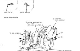
Side Air Scoop/Side Sill Panel/Side Step Panel Replacement CAUTION: When prying with a flat tip screwdriver, wrap it with protective tape or a shop towel to prevent damage. NOTE: • Take care not to scratch the body and related parts. • Do not drop the special mounting nuts inside the body. Disassemble in numbered sequence. […]

Categories
Electrical

nsxb23139a.pdf

Seat Belt Reminder System Seat Belt Switch Test 1. Slide the driver’s seat all the way forward, then dis- connect the 2-P connector from the seat belt switch. 2. Check continuity between the A and B terminals with the driver’s seat belt buckled and unbuckled. • There should be no continuity with the driver’s seat […]

Categories
Cylinder Head & Valve Train

nsxb06038a.pdf

Valve Seats Reconditioning 1. Renew the valve seats in the cylinder head using a valve seat grinder. NOTE: If guides are worn (see page 6-39), replace them (see page 6-40) before grinding the valve seats. 2. Carefully grind a 45° seat, removing only enough material to ensure a smooth and concentric seat. 3. Bevel the […]

Categories
Manual Transmission

nsxb13041a.pdf

Mainshaft Thrust Shim Adjustment 1. Remove the thrust shim and oil guide plate from the transmission housing. 2. Install the mainshaft in the transmission housing. NOTE: Do not install the clutch housing side ball bearing. 3. Measure distance between the end of the transmission housing and mainshaft. NOTE: • Use a straight edge and feeler […]

Categories
Engine Lubrication

nsxb08002a.pdf

Special Tools 8-9 8-5 Special Tools Mam Menu Table of Contents 1 Ref. No. Tool Number ‘ Description my Page Reference ≓ ↽ ⇠ ⋈ „ ↽ fl ↟ ↜⋡ ↽↽ ‚ (1) O7GAD—PH70201 он Seal Driver 1 ‘ 8-9 (Í) 07912 — 6110001 Oil Filter Wrench 1 8-5 8-2 Attachments nsxb08002a (28 kB)

Categories
Engine Lubrication

nsxb08007a.pdf

Oil Pump Overhaul NOTE: • Use new O-rings when reassembling. • Apply oil to O-rings before installation. 6 x 1.0 mm 6 N-m (0.6 kg-m. 4 Ib-ft) PUMP COVER Inspection, page 8-8, 8-9 PUMP HOUSING Inspection, page 8-8, 8-9 OIL SEAL Installation, page 8-9 Replace. OUTER ROTOR Inspection, page 8-8, 8-9 SEALING BOLT 18 mm […]

Categories
Electrical

nsxb23126a.pdf

Gauge Assembly Removal SRS components are located in this area. Review the SRS component locations, precautions, and procedures in the SRS section 24 before performing repairs or service. 1. Remove the dashboard lower cover, and disconnect the floor wire harness connectors. 2. Remove the two screws, then remove the dashboard lower pad from the dashboard. […]

Categories
Electrical

nsxb23136a.pdf

Engine Coolant Temperature (ECT) Gauge ECT Gauge Test 1. Before testing, check the No. 5 (1 5 A) fuse in the under-dash fuse box. 2. Make sure the ignition switch is OFF, then discon- nect the YEL/GRN wire from the ECT sending unit and ground it with a jumper wire. YEL/GRN WIRE ECT SENDING UNIT […]

Categories
Uncategorized

nsx13index.pdf

Manual Transmission Special Tools 13−2. . . . . . . . . . . . . . . . . . Maintenance Transmission Oil ’91−’95 Models 13−3. . . . . . . . . . ’96 Model 13−2. . . . . . . . . . . . . . . Back−up […]

Categories
Uncategorized

nsx11indxa.pdf

Fuel and Emissions (’95−’96 Models) Special Tools 11−2. . . . . . . . . . . . . . . . . Component Location Index 11−3. . . . System Description Vacuum Connections 11−7. . . . . . Electrical Connections 11−10. . . . . System Connectors Engine Compartment, Right Side 11−24. […]