Adjustment
1. Remove the thrust shim and oil guide plate from the
transmission housing.
2. Install the mainshaft in the transmission housing.
NOTE: Do not install the clutch housing side ball
bearing.
3. Measure distance between the end of the
transmission housing and mainshaft.
NOTE:
• Use a straight edge and feeler gauge.
• Measure at three locations and average the
readings.
4. Set the mainshaft ball bearing in the clutch hous-
ing, and measure distance between the
surfaces of the clutch housing and the bearing in-
ner race.
NOTE:
• Use a straight edge and feeler gauge.
• Measure at three locations and average the
readings.
• Do not install the spring washer.
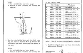
5. Select the proper thrust shim on the basis of the
following calculations.
NOTE: Do not use more than two thrust shims.
(Basic Formula)
A + B — 0.99 mm = shim thickness (max.)
A + B – 1.06 mm = shim thickness (min.)
A – C – 0.99 mm = shim thickness (max.)
A – C – 1.06 mm = shim thickness (min.)
82 mm THRUST SHIM
NOTE: Clean all the parts thoroughly before installation
6. Install the oil guide plate and thrust shim into the
transmission housing.
TRANSMISSION
HOUSING THRUST SHIM
OIL GUIDE PLATE
13-41
Mainshaft Thrust Shim
Adjustment
7. Install the ball bearing onto the mainshaft using the
special tools, then install the 75 mm spring washer
and mainshaft assembly into the clutch housing.
DRIVER, 40 mm I.D.
07746 – 0030100
ATTACHMENT, 35 mm I.D.
07746 – 0030400
BALL BEARING
8. Install the transmission housing.
Torque: 45 N-m (4.5 kg-m, 33 Ib-ft)
9. Check the thrust clearance in the manner described
below.
NOTE: Carry out the measurement at normal room
temperature.
a. Slide the mainshaft base over the mainshaft,
b. Attach the mainshaft holder to the mainshaft as
follows:
• Back-out the mainshaft holder bolt and
loosen the two hex bolts.
• Fit the holder over the mainshaft so its lip is
towards the transmission.
• Align the mainshaft holder’s lip around the
groove at the inside of the mainshaft splines,
then tighten the hex bolts.
HEX BOLT
MAINSHAFT
HOLDER BOLT
MAINSHAFT
HOLDER
07GAJ – PG20110
MAINSHAFT BASE
07GAJ – PG20130
c. Seat the mainshaft fully by tapping its end
with a plastic hammer.
d. Thread the mainshaft holder bolt in until it
just contacts the wide surface of the main-
shaft base.
e. Zero a dial gauge on the end of the mainshaft.
DIAL GAUGE
f. Turn the mainshaft holder bolt clockwise; stop
turning when the dial gauge has reached its
maximum movement. The reading on dial
gauge is the amount of mainshaft end play.
CAUTION: Turning the shaft holder bolt more
than 60 degrees after the needle of the dial
gauge stops moving may damage the
transmission.
g. If the reading is within the standard, the
clearance is correct.
If the reading is not within the standard, recheck
the shim thickness.
Standard: 0.14-0.21 mm (0.006-0.008 in)