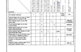
B lo w n N o. 5 ( 1 0 A ) fu se (In t he u nd er -d as h fu se b ox ) B lo w n N o. 3 4 (1 5 A ) fu se (In t he u nd er -d as h fu se b ox […]
Categories
nsxd23150a.pdf
B lo w n N o. 5 ( 1 0 A ) fu se (In t he u nd er -d as h fu se b ox ) B lo w n N o. 3 4 (1 5 A ) fu se (In t he u nd er -d as h fu se b ox […]
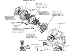
Illustrated Index NOTE: Whenever the transmission is removed, clean and grease the release bearing sliding surface. If the parts marked * are removed, the clutch hydraulic system must be bled. Bleed the clutch hydraulic system (see page 12-6). Inspect the hoses for damage, leaks, interference, and twisting. FLYWHEEL Inspection, page 12-16 Replacement, page 12-17 MID […]
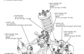
Front Suspension Torque Specifications CAUTION: • Replace the self-locking nuts after removal. • Replace the self-locking bolts if you can easily thread a non-self-locking nut past their nylon locking inserts. (It should require 1 N-m (0.1 kg-m, 0.7 Ib-ft) of torque to turn the test nut on the bolt). • The vehicle should be on […]
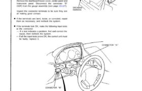
— If all the input tests prove OK, the control unit must CAUTION: All SRS wiring harnesses are covered with yellow out- er insulation. Before disconnecting any part of the SRS wire hap ness, install the short connectors (see page 24-10(’93-’96)) Replace the entire affected SRS harness assembly if it has an open circuit or […]
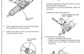
Steering Gearbox Inspection 1. Carefully clamp the gearbox in a vise with soft jaws. 2. Remove the boot bands. BOOT BAND Replace. 3. Pull the boots away from the ends of the gearbox, then unbend the tie-rod lock washers. 4. Hold the rack with a wrench, and unscrew the tie- rods with another wrench. LOCK […]
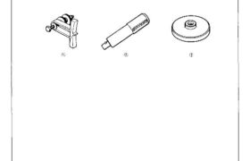
Special Tools 7-6 7-18 7-18 Mam Menu Table of Contents Special Tools 1 (¿j Ref. No. Tool Number Description Qty Page Reference G) 07LAB — PV00100 Ring Gear Holder 1 7—6 or 07924 — PD20003 ® 07749 — 0010000 Driver ‘I 7-18 ® 07948 — 5300101 Driver Attachment 1 7-18 G:) Attachments nsxb07002a (31 kB)
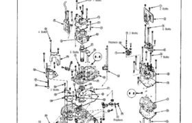
Replace. 7 Bolts 5 Bolts 2 Bolts 2 Bolts Replace. 2 Bolts 5 Bolts 4 Bolts 7 Bolts Valve Body Removal NOTE: 1. Remove the valve body in the following numbered sequence. CAUTION: Do not use a magnet to remove the check balls; it may magnetize the balls. Clean all parts thoroughly in solvent or […]
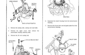
Transmission Housing Removal NOTE: Place the clutch housing on two pieces of wood thick enough to keep the mainshaft from hitting the workbench. 1. Remove the back-up light switch, neutral switch and speed sensor. SPEED SENSOR NEUTRAL SWITCH BACK-UP LIGHT SWITCH 2. Remove the sealing bolts, springs and steel balls. 3. Remove the upper cover, […]
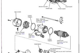
Starting System CAUTION: Disconnect the ground cable from the bat- tery before removing the starter. SOLENOID PLUNGER Inspection, page 23-86 STARTER SOLENOID Test, page 23-81 OVERRUNNING CLUTCH ASSEMBLY BRUSH HOLDER ARMATURE IDLER GEAR PINION GEAR END COVER O-RING Replace. FIELD WINDING/ ARMATURE HOUSING Test, page 23-86 IDLER GEAR SOLENOID HOUSING HARNESS CLIP BRACKET STEEL BALL […]
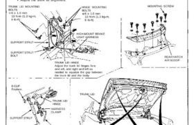
Trunk Lid Replacement/Adjustment 1. Remove the mounting screws, then remove the rear hatch air scoop. 2. Disconnect the high-mount brake light harness connector, and remove the harness clamp from the support strut. 3. Remove the trunk lid by removing the trunk lid mounting bolts. 4. Installation is the reverse of the removal procedure. NOTE: • […]