CAUTION:
All SRS wiring harnesses are covered with yellow out-
er insulation.
Before disconnecting any part of the SRS wire hap
ness, install the short connectors (see page 24-10(’93-’96))
Replace the entire affected SRS harness assembly if
it has an open circuit or damaged wiring.
After installing the gauge assembly, recheck the oper-
ation of the SRS indicator light.
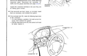
Remove the dashboard lower cover, center panel and
instrument panel. Disconnect the connector “B”
OOP) from the gauge assembly (see page 23-127).
Inspect the connector terminals to be sure they are
all making good contact.
If the terminals are bent, loose, or corroded, repair
them as necessary, and recheck the system.
If the terminals look OK, make the following input tests
at the connector.
— If a test indicates a problem, find and correct the
cause, then recheck the system.
be faulty; replace it.
CONNECTOR “A” (Carries the SRS indicator signal)
SRS MAIN
HARNESS
CONNECTOR “A’
YEL RED/ELK GRN/YEL
LT BLU
View from wire side
CONNECTOR “B”
BLK RED LT GRN LT GRN/WHT
YEL/BLU
GRY/WHT GRNYEL/BLK
BRN/BLK
A/T Gear Position Indicator
Indicator Input Test
Main Menu
Table of Contents
Test condition
Test: Desired result
Possible cause if result is not obtained
1 BLK Under all conditions, Check for continuity to ground: – Poor ground (G401, G402).
There should be continuity. – An open in the wire.
2 YEL Ignition switch ON. Check for voltage to ground: – Blown No. 5 (10 A) fuss.
There should be battery voltage. – An open in the wire.
3 GRY/WHT Shift lever in position P. Check for continuity to ground: – Faulty A/T gear position switch.
NOTE: Don’t push the There should be continuity. – Poor ground (G401. G402),
brake pedal. There should be no continuity in ∙ An open in the wire.
LT BLU Shift lever in position R. any ‘ma’ ⇂≖∘∺⋯∘⊓⊲
GRN Shift lever in position Д.
BEN/BLK Shift lever in position i.
GRN/YEL Shift lever in position 2 .
LT GRN/ Shift lever in position 1 .
WHT
4 REDIBLK Combination light Check for voltage between – Faulty dash lights brightness
and RED switch ON and dash RED/BLK and RED terminals: control system.
lights brightness con- There should be battery voltage. – An open in the wire.
trol dial on full bright.
5 YEL/BLK Ignition switch ON Check for voltage to ground: – Faulty D switch.
and shift lever in any There should be battery voltage for – Faulty A/T gear position switch.
position except В. two seconds after the ignition – Faulty transmission control module
switch is turned ON, and less than (TCM).
1 V two seconds later. – An open in the wire.
6 YEL/BLU Ignition switch ON Check for voltage to ground: ∙ Faulty D switch.
and shift lever in any There should be less than 1 V for – Faulty AIT gear position switch.
position except D . two seconds after the ignition – Faulty transmission control module
switch is turned ON, and more than (TCM).
5 V two seconds later. – An open in the wire.
7 LT GRN Ignition switch ON. Check for voltage to ground: – Faulty ECM and transmission
There should be more than 11 V. control module (TCM).
∙ ∧∏ open in the wire.
23-155