Inspection
1. Carefully clamp the gearbox in a vise with soft jaws.
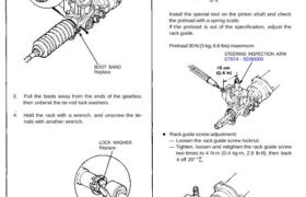
2. Remove the boot bands.
BOOT BAND
Replace.
3. Pull the boots away from the ends of the gearbox,
then unbend the tie-rod lock washers.
4. Hold the rack with a wrench, and unscrew the tie-
rods with another wrench.
LOCK WASHER
Replace.
• Preload inspection:
Slide the steering rack in the cylinder until the end of
the rack projects 60 mm (2.4 in) from the cylinder
end. Inspection is made near this rack position.
CYLINDER
RACK
Install the special tool on the pinion shaft and check
the preload with a spring scale.
If the preload is out of the specification, adjust the
rack guide.
Preload 30 N (3 kg, 6.6 Ibs) maximum
STEERING INSPECTION ARM
07974 – SD90000
Rack guide screw adjustment:
— Loosen the rack guide screw locknut.
— Tighten, loosen and retighten the rack guide screw
two times to 4 N-m (0.4 kg-m, 2.9 Ib-ft), then back
it off 20°
Retighten the locknut while holding the rack
guide screw with a wrench.
LOCKNUT
25 N-m (2.5 kg-m, 18 Ib-ft)
LOCKNUT WRENCH, 40 mm
07916 – SA50001
Tie-rod installation:
5. Screw each rack end into the rack while holding the
lock washer so its tabs are in the slots in the rack
end.
NOTE: Install the stopper washer with the cham-
fered side facing out.
LOCK WASHER
Replace.
TAB
RACK END STOPPER WASHER
6. Tighten the rack end securely, then bend the lock
washer back against the flat on the flange as shown.
NOTE: Coat the stopper washer with grease suffi-
ciently.
RACK END
55 N-m
(5.5 kg-m, 40 Ib-ft)
SLOT
Steering Gearbox
Inspection
7. Install the boots on the rack end with the tube clamps.
NOTE:
• Coat the rack end and inside of the boot with the
grease.
• Before installing the boot, be sure that the pres-
sure inside of the boot is the atmospheric pres-
sure.
• Install the boot band with the rack in the straight
ahead condition (right and left tie-rods are equal
in length).
BOOT
TUBE CLAMP
STEERING GREASE
(Honda P/N 08733-B070E)
Coat the inside of the boot.
SILICONE GREASE
Coat the sliding surface
of the rack end.
8. Install the new boot bands on the boot, and bend
both sets of locking tabs. Lightly tap on the doubled
portions to reduce their height.
NOTE: After assembling, slide the rack right and
left to be certain that the boots are not deformed or
twisted.
LOCKING TABS
BOOT BAND
Replace.
9. If the tie-rod ends were removed, install the tie-rods
on the right and left rack ends and screw them in
until the threaded section is 11 mm (0.4 in) in length.
11 mm (0.4 in)
LOCKNUT
Hand tighten.
TIE-ROD END
10. Install the gearbox and the front crossbeam in the
reverse order removal (see page 17-57).
11. Check the wheel alignment and adjust if necessary
(see section 18).