Categories
Electrical

nsxd23292a.pdf

Cruise Control Description The cruise control system uses mechanically and elec- trically operated devices to maintain vehicle speed at a setting selected by the driver. The cruise control unit receives command signals from the cruise control main switch and the cruise control set/resume switch. It receives information about operating conditions from the brake switch, ECM, […]

Categories
Suspension

nsxb18031a.pdf

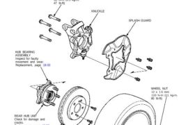
Hub Replacement NOTE: • Use only genuine Honda wheel weights for aluminum wheels. Non-genuine wheel weights may corrode and damage the aluminum wheels. • On the aluminum wheels, remove the center cap from inside of the wheel after removing the wheel. • Before installing the brake disc, clean the mating surface of the rear hub […]

Categories
Manual Transmission

nsxd13043a.pdf

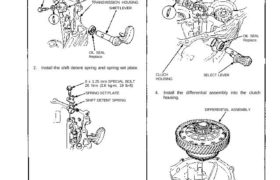
Transmission Reassembly 1. Install the oil seal, shift arm, and shift lever in the transmission housing. 8 x 1.0 mm SPECIAL BOLT 32 N.m (3.2 kg-m, 23 Ib-ft) SPRING WASHER SHIFT ARM TRANSMISSION HOUSING SHIFT LEVER OIL SEAL Replace. 2. Install the shift detent spring and spring set plate. 8 x 1.25 mm SPECIAL BOLT […]

Categories
Fuel & Emissions

nsxd11040a.pdf

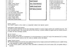
PGM-FI System System Description INPUTS ENGINE CONTROL MODULE (ECM) OUTPUTS FRONT HO2S REAR HO2S MAP Sensor CKP/CYP Sensor ECT Sensor TP Sensor IAT Sensor VSS FRONT KS REAR KS Ignition Timing Adjuster EGR Valve Lift Sensor A/T Fl Signals TCS Signals Starter Signal ALT FR Signal Air Conditioning Signal A/T Gear Position Switch Signal Neutral […]

Categories
Fuel & Emissions

nsxb11052a.pdf

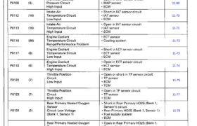
These DTCs will be indicated by the blinking of the Malfunction Indicator Lamp (MIL) with the SCS service connector connected Troubleshooting Diagnostic Trouble Code (DTC) Chart 11-65 11-67 11-69 11-70 11-71 11-72 11-73 11-74 11-75 11-77 11-78 11-80 11-81 11-85 11-82 11-83 11-84 11-85 11-78 11-80 11-81 11-85 11-82 11-83 11-84 11-85 11-87 11-87 Main […]

Categories
Brakes & ABS

nsxb19061a.pdf

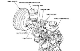
Hydraulic System Hydraulic Connections CAUTION: Do not spill brake fluid on the car; it may damage the paint; if brake fluid does contact the paint, wash it off immediately with water. Attachments nsxb19061a (54 kB)

Categories
Steering

nsxd17041a.pdf

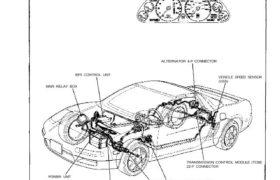
Wiring Locations EPS CONTROL UNIT MAIN RELAY BOX POWER UNIT TORQUE SENSOR 6-P CONNECTOR/ STEERING WHEEL SPEED SENSOR 4-P CONNECTOR STEERING GEARBOX (TORQUE SENSOR/STEERING WHEEL SPEED SENSOR) UNDER-DASH FUSE/RELAY BOX TRANSMISSION CONTROL MODULE (TCM) 22-P CONNECTOR VEHICLE SPEED SENSOR (VSS) ALTERNATOR 4-P CONNECTOR EPS INDICATOR LIGHT Attachments nsxd17041a (108 kB)

Categories
Electrical

nsxb23209a.pdf

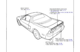
Brake Lights Component Location Index BRAKE SWITCH Test, page 23-211 HIGH MOUNT BRAKE LIGHT (LED) LED Replacement, page 23-212 (’94-’96) (’91-’93) Replacement, page 23-212 (’94-’96) (’91-’93) Test, page 23-211 RIGHT TAILLIGHT Bulb Replacement, page 23-196 Failure Sensor Test, page 23-153 LEFT TAILLIGHT Bulb Replacement, page 23-196 Failure Sensor Test, page 23-153 Attachments nsxb23209a (41 kB)

Categories
Brakes & ABS

nsxe19061a.pdf

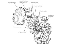
Hydraulic System Hydraulic Connections CAUTION: Do not spill brake fluid on the car; it may damage the paint; if brake fluid does contact the paint, wash it off immediately with water. BRAKE BOOSTER MASTER CYLINDER RESERVOIR TANK To right rear brake To left rear brake To left front brake MASTER CYLINDER To right front brake […]

Categories
Electrical

nsxe23144a.pdf

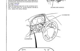
CAUTION: All SRS electrical wiring harnesses are covered with yellow outer Insulation. Before disconnecting the SRS wire harness, Install the short connector on the airbag (see page STET). Replace the entire affected SRS harness assembly if it has an open circuit or damaged wiring. After installation of the gauge assembly, recheck the operation of the […]