connected
Troubleshooting
Diagnostic Trouble Code (DTC) Chart
11-65
11-67
11-69
11-70
11-71
11-72
11-73
11-74
11-75
11-77
11-78
11-80
11-81
11-85
11-82
11-83
11-84
11-85
11-78
11-80
11-81
11-85
11-82
11-83
11-84
11-85
11-87
11-87
Main Menu Table of Contents b
O
DTC .
(MIL indication) Detection Item Probable Cause Page
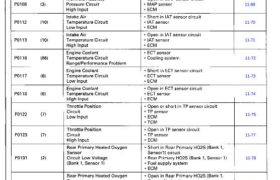
Rear Secondary Heated Oxygen – Short in Rear Secondary H025 (Bank 1,
Sensor Sensor 2) circuit
P0137 (64) Circuit Low Voltage – Rear Secondary HO2S (Bank 1, Sensor 2) 11’82
(Bank 1, Sensor 2) – ECM
Rear Secondary Heated oxygen – Open in Rear Secondary H025 (Bank ‘I,
Sensor Sensor 2) circuit
P0138 (64) Circuit High Voltage – Rear Secondary H025 (Bank 1 ‚ Sensor 2) 11’83
(Bank 1, Sensor 2) – ECM
Rear Secondary Heated Oxygen – Rear Secondary H028 (Bank 1, Sensor 2)
Sensor
P0139 (64) Slow Response 11-84
(Bank 1, Sensor 2)
Rear Secondary Heated Oxygen – Open or short in Rear Secondary HO2S
Sensor Heater (Bank 1, Sensor 2) heater circuit
P0141 (бы Circuit Malfunction – ECM 11’85
(Bank 1, Sensor 2)
Front Primary Heated – Short in Front Primary HOZS (Bank 2,
Oxygen Sensor Circuit Sensor 1) circuit
P0151 (1) Low Voltage – Front Primary H028 (Bank 2, Sensor 1) 11-78
(Bank 2, Sensor 1) – Fuel supply system
– ECM
Front Primary Heated – Open in Front Primary H025 (Bank 2,
Oxygen Sensor Circuit Sensor 1) circuit
P0152 (1’ High Voltage – Front Primary H025 (Bank 2, Sensor 1i 11’80
(Bank 2, Sensor 1) – ECM V V
Front Primary Heated – Front Primary HOZS (Bank 2, Sensor 1)
Oxygen Sensor – Exhaust system
P0153 (61) Slow Response 11-81
(Bank 2, Sensor 1)
Front Primary Heated – Open or short in Front Primary H025
Oxygen Sensor Heater (Bank 2, Sensor 1) heater circuit
P0155 (41) Circuit Malfunction – ECM 11‘85
(Bank 2, Sensor 1)
Front Secondary Heated ∙ Short in Front Secondary H025 (Bank 2,
Oxygen Sensor Circuit Sensor 2) circuit
P0157 ‘63) Low Voltage – Front Secondary H025 (Bank 2, Sensor 2) 11’82
(Bank 2, Sensor 2) – ECM i
Front Secondary Heated ∙ Open in Front Secondary H025 (Bank 2,
Oxygen Sensor Circuit Sensor 2) circuit
P0158 (63) High Voltage – Front Secondary H025 (Bank 2, Sensor 2) 11-83
(Bank 2, Sensor 2) – ECM
Front Secondary Heated – Front Secondary H025 (Bank 2, Sensor 2)
Oxygen Sensor
P0159 (63) Slow Response 11-84
(Bank 2, Sensor 2)
Front Secondary Heated – Open or short in Front Secondary H025
Oxygen Sensor Heater (Bank 2, Sensor 2) heater circuit
P0161 (65’ Circuit Malfunction – ECM 11’85
(Bank 2, Sensor 2)
System Too Lean – Fuel supply system
[Rear Bank (Bank 1)] – Rear Primary H025 (Bank 1, Sensor 1)
– MAP sensor
P0171 (46) – Contaminated fuel ↕↕⊶∂⊺
∙ Valve clearance
– Exhaust leakage
System Too Rich – Fuel supply system
[Rear Bank (Bank 1)] – Rear Primary H025 (Bank 1, sensor1)
P0172 (46) – MAP sensor 11—87
∙ Contaminated fuel
– Valve clearance
(cont’d)
11-53
Diagnostic Trouble Code (DTC) Chart
Troubleshooting
11-87
11-87
11-89
11-89
11-100
11-100
11-162
11-160
11-160
11-168
11-102
Section 14
indicator light and the Malfunction Indicator Lamp (MIL) may come on simultaneously.The
11-103
11-103
11-90
11-109
11-109
11-111
11-111
11-114
11-114
11-114
Section 6
Section 6
Main Menu
Table of Contents
DTC .
(MIL indication) Detection Item Probable Cause
Barometric – ECM (Barc sensorl
P1107 (13) Pressure Circuit
Low Input
Barometric – ECM (Baro sensor)
P1108 (13) Pressure Circuit
High Input
Misfire – Fuel injector
P1201 7 — Cylinder 1 – Fuel injector circuit
P1202 72 — Cylinder 2 – Ignition system
P1203 73 – Cylinder 3 – Low compression
P1204 74 — Cylinder 4 – Valve clearance
P1205 75 A Cylinder 5
P1206 76 — Cylinder 6
Detected
Throttle Valve Control – Open or short in Throttle Valve Control
Motor Circuit 1 Motor circuit 1
P1241 (40) Malfunction – Throttle Valve Control Motor 11’109
– ECM
Throttle Valve Control – Open or short in Throttle Valve Control
Motor Circuit 2 g Motor circuit 2
P1242 (40) Malfunction – Throttle Valve Control Motor 11’109
l – ECM
Throttle Position ⋮ ∙ Throttle Valve
P1243 (40) Insufficient – TP sensor 11-111
– Throttle Valve Control Motor
P1244 (40) Closest Throttle Posmon ∙ Throttle Valve ∐∙⋮∣⋅∐
Insufficient ∙ TP sensor
Accelerator Position – Open or short in Accelerator Position
Sensor 1 Circuit sensor1 circuit
P1246 (37) Malfunction – Accelerator Position sensor 11’114
– ECM
Accelerator Position – Open or short in Accelerator Position
Sensor 2 Circuit sensor 2 circuit ∎
P1247 (37) Malfunction – Accelerator Position sensor 11’114
– ECM
Accelerator Position – Accelerator Position sensor
P1248 (37) Sensor 1 and 2 11-114
Incorrect Correlation
VTEC System V‘ – Open or short in Rear VTEC Solenoid
Malfunction Valve circuit
[Rear Bank (Bank 1)] ⋅ Rear VTEC Solenoid Valve
P1259 (52) – Open or short in Rear VTEC Pressure Section 6
Switch circuit
– Rear VTEC Pressure Switch
– ECM
VTEC System – Open or short in Front VTEC Solenoid
Malfunction Valve circuit
[Front Bank (Bank 2l] – Front VTEC Solenoid Valve
P1279 (22) – Open or short in Front VTEC Pressure Section 6
Switch circuit
⋅ Front VTEC Pressure Switch
– ECM
lccnt’d)
11-55
11-94
11-90
11-96
11-96
11-98
11-98
11-100
11-100
11-100
11-100
11-100
11-100
11-170
Diagnostic Trouble Code (DTC) Chart
Troubleshooting
Main Menu
Table of Contents
Troubleshooting
— Diagnostic Trouble Code (DTC) Chart (cont’d)
DTC .
(MIL indication) Detection Item Probable Cause Page
1 Random Misfire v ignition system
72 ⋅ Fuel supply system
P1300 73 – MAP sensor
74 – EGR system 11-94
75 – Contaminated fuel
76 ∙ Lack of fuel
—— Cylinder 1 – ignition system
P1301 1 — Cylinder 2
P1302 72 — Cylinder 3
P1303 73 — Cylinder 4 11 90
P1304 74 — Cylinder 5 −
P1305 75 — Cylinder 6
P1306 7s Misfire
Detected
Spark Plug Voltage – Open or short in Spark Plug Voltage
Detection Circuit Detection Module circuit
P1316 (79) Malfunction – Spark Plug Voltage Detection Module 11’96
[Front Bank (Bank 2)] ∙ ∣⋮∁∣⋁∣
Spark Plug Voltage ⋅ Open or short in Spark Plug Voltage
Detection Circuit Detection Module circuit
P1317 (79) Malfunction – Spark Plug Voltage Detection Module 11’96
[Rear Bank (Bank 1)] – ECM
Spark Plug Voltage ∙ Open or short in Spark Plug Voltage
Detection Module Reset Detection Module Reset circuit
P1318 (79) Circuit Malfunction – Spark Plug Voltage Detection Module 11’98
[Front Bank (Bank 2)] ∙ ECM
Spark Plug Voltage – Open or short in Spark Plug Voltage
Detection Module Reset Detection Module Reset circuit
P1319 (79) Circuit Malfunction ∙ Spark Plug Voltage Detection Module 11’98
[Rear Bank (Bank 1)] ∙ ECM
Crankshaft Position ∙ Crankshaft Position Sensor B
P1336 (54) Sensor B (- Timing belt skipping teeth) 11—100
Range/Performance
Crankshaft Position – Crankshaft Position Sensor B
P1337 (54) Sensor B Circuit – Crankshaft Position Sensor B circuit 11-100
Low input ∙ ECM
Cylinder Position – Cylinder Position Sensor A
P1381 (9) Sensor A 11-100
intermittent interruption
Cylinder Position – Cylinder Position Sensor A
P1382 (9) Sensor A No Signal – Cylinder Position Sensor A circuit 11-100
– ECM
Cylinder Position – Cylinder Position Sensor B
P1386 (59) Sensor B 11-100
intermittent interruption
Cylinder Position – Cylinder Position Sensor B
P1387 (59) Sensor B No Signal ∙ Cylinder Position Sensor B circuit 11-100
∙ ECM
Evaporative ∙ EVAP Purge Flow Switch
Emission ∙ EVAP Purge Flow Switch circuit
P1459 (92) Purge Flow Switch – Tubing 11’170
Malfunction ∙ ECM
11-56
indicator light and the Malfunction Indicator Lamp (MIL) may come on simultaneously.The
11-163
11-165
11-104
11-104
11-105
11-105
Section 19
Section 19
Section 14
Main Menu
Table of Contents
(MIL iîliîation) Detection Item Probable Cause Page
EGR Valve – EGR valve (with lift sensor)
Lift Insufficient – EGR valve lift sensor circuit
Detected – EGR control solenoid valve
P1491 “2) – EGR control solenoid valve circuit 11’163
– EGR line
– ECM
EGR Valve ∙ EGR valve (with lift sensor)
P1498 (12) Lift Sensor – EGR valve lift sensor circuit 11-165
High Voltage – ECM
Engine Control – ECM
P1607 (-) Module Internal 11-104
Circuit Failure A
Engine Control – ECM
P1608 (—) Module Internal 11-104
Circuit Failure B
А/Т Fl ⋅ А/Г Fl Data Line
P1671 (31) Data Line ∙ TCM 11-105
No Signal – ECM
AIT Fl – AIT FI Data Line
P1672 (31) Data Line – TCM 11-105
Failure ⋅ ECM
TCS Fl ∙ TCS Fl Data Line
P1676 (35) Data Line – TCS Control Unit Section 19
N0 Signal ⋅ ∊∁↿∨∣
TCS FI – TCS Fl Data Line
P1677 (35) Data Line – TCS Control Unit Section 19
Failure – ECM
P1705 Automatic
P1706 Transaxle
P1753
P1758
P1768
P1788 (70)* —— Section 14
P1790
P1791
P1792
P1793
P1795
*z The@ indicator light and the Malfunction Indicator Lamp (MIL) may come on simultaneously.
11-57