CAUTION:
All SRS electrical wiring harnesses are covered with
yellow outer Insulation.
Before disconnecting the SRS wire harness, Install
the short connector on the airbag (see page STET).
Replace the entire affected SRS harness assembly
if it has an open circuit or damaged wiring.
After installation of the gauge assembly, recheck the
operation of the SRS indicator light.
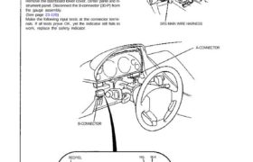
Remove the dashboard lower cover, center panel and in-
strument panel. Disconnect the 8-connector (30-P) from
the gauge assembly.
(See page 23-126)
Make the following input tests at the connector termi-
nals. If all tests prove OK, yet the indicator stilt fails to
work, replace the safety indicator.
A-CONNECTOR (Carries the SRS indicator signal)
SRS MAIN WIRE HARNESS
A-CONNECTOR
YEL
GRN/RED
View from terminal side
Safety Indicator
Indicator Input Test
B-CONNECTOR
RED/YEL
BLK/WHT
GRN/BLK
BLU GRN/BLU
BLK
All SRS electrical wiring harnesses are covered with
yellow outer Insulation.
Before disconnecting the SRS wire harness, Install
the short connector on the airbag (see page STET).
Replace the entire affected SRS harness assembly
if it has an open circuit or damaged wiring.
After installation of the gauge assembly, recheck the
operation of the SRS indicator light.
Remove the dashboard lower cover, center panel and in-
strument panel. Disconnect the 8-connector (30-P) from
the gauge assembly.
(See page 23-126)
Make the following input tests at the connector termi-
nals. If all tests prove OK, yet the indicator stilt fails to
work, replace the safety indicator.
A-CONNECTOR (Carries the SRS indicator signal)
SRS MAIN WIRE HARNESS
A-CONNECTOR
YEL
GRN/RED
View from terminal side
Safety Indicator
Indicator Input Test
B-CONNECTOR
RED/YEL
BLK/WHT
GRN/BLK
BLU GRN/BLU
BLK
*: Terminal is floor wire harness side.
No. Wire Test condition Test: desired result Possible cause (if result is not obtained)