Ignition Timing Inspection
SRS components are located in this area. Review the SRS
component locations, precautions, and procedures in the
SRS section 24 before performing repairs or service.
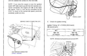
1. Pull out the service check connector located under
the middle of the dash. Connect the BLU and BRN/
BLK terminals with the SCS service connector.
2. Start the engine. Hold the engine at 3,000 rpm with
no load (A/T in [N] or 0 position, M/T in neutral)
until the radiator fan comes on, then let it idle.
NOTE: If you stop the engine or turn the ignition
switch OFF after warm-up with the SCS service con-
nector connected, the engine will idle at the base
idle speed. That is, it will not be controlled by the
ECM. To return to the normal idle speed, press the
accelerator pedal one time.
SERVICE CHECK CONNECTOR (2-P)
SCS SERVICE CONNECTOR
07PAZ – 0010100
3. Check the idle speed (see page 23-92).
4. Connect a timing light to the service loop; while the
engine idles, point the light toward the pointer on
the timing belt cover.
SERVICE LOOP
TIMING LIGHT
5. Check the ignition timing.
Ignition Timing: 15° + 2° BTDC (RED mark)
Idle Speed (rpm):
NOTE: All electrical systems are turned OFF.
POINTER
WHITE MARK
RED MARK
CRANKSHAFT PULLEY
6. If it is necessary to adjust the ignition timing, replace
the ECM.
7. Remove the SCS service connector from the service
check connector.
SRS components are located in this area. Review the SRS
component locations, precautions, and procedures in the
SRS section 24 before performing repairs or service.
1. Pull out the service check connector located under
the middle of the dash. Connect the BLU and BRN/
BLK terminals with the SCS service connector.
2. Start the engine. Hold the engine at 3,000 rpm with
no load (A/T in [N] or 0 position, M/T in neutral)
until the radiator fan comes on, then let it idle.
NOTE: If you stop the engine or turn the ignition
switch OFF after warm-up with the SCS service con-
nector connected, the engine will idle at the base
idle speed. That is, it will not be controlled by the
ECM. To return to the normal idle speed, press the
accelerator pedal one time.
SERVICE CHECK CONNECTOR (2-P)
SCS SERVICE CONNECTOR
07PAZ – 0010100
3. Check the idle speed (see page 23-92).
4. Connect a timing light to the service loop; while the
engine idles, point the light toward the pointer on
the timing belt cover.
SERVICE LOOP
TIMING LIGHT
5. Check the ignition timing.
Ignition Timing: 15° + 2° BTDC (RED mark)
Idle Speed (rpm):
NOTE: All electrical systems are turned OFF.
POINTER
WHITE MARK
RED MARK
CRANKSHAFT PULLEY
6. If it is necessary to adjust the ignition timing, replace
the ECM.
7. Remove the SCS service connector from the service
check connector.