Categories
Cylinder Head & Valve Train

nsxd06047b.pdf

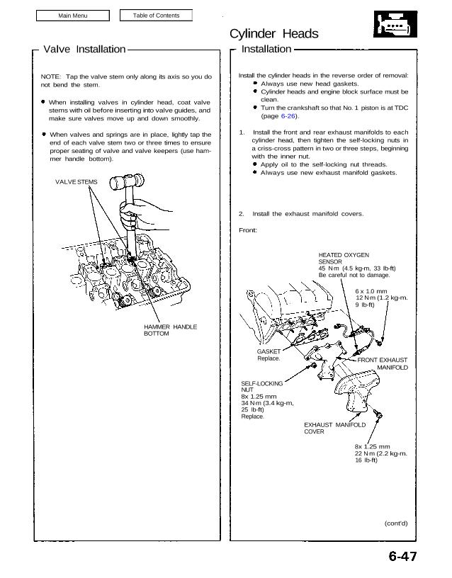
Cylinder Heads Installation 2. Install the exhaust manifold covers. Front: HEATED OXYGEN SENSOR 45 N.m (4.5 kg-m, 33 Ib-ft) Be careful not to damage. 6 x 1.0 mm 12 N.m (1.2 kg-m. 9 Ib-ft) GASKET Replace. SELF-LOCKING NUT 8x 1.25 mm 34 N.m (3.4 kg-m, 25 Ib-ft) Replace. EXHAUST MANIFOLD COVER (cont’d) 8x 1.25 mm […]

Categories
Body

nsxb20029a.pdf

Installation 1. Scrape old adhesive smooth with a knife to a thickness of about 2 mm (0.08 in) on the bonding surface around the entire rear window flange. NOTE: • Do not scrape down to the painted surface of the body; damaged paint will interfere with pro- per bonding. • Mask off surrounding surfaces before […]

Categories
Electrical

nsxb23305a.pdf

Main Switch Replacement SRS components are located in this area. Review the SRS component locations, precautions, and procedures in the SRS section 24 before performing repairs or ser- vice. 1. Remove the dashboard lower cover, and disconnect the connectors. 2. Remove the dashboard lower pad. DASHBOARD LOWER COVER DASHBOARD LOWER PAD 3. Remove the tilt […]

Categories
Electrical

nsxb23186a.pdf

Lighting System Retractor Motor Replacement CAUTION: • Halogen headlights can become very hot in use; do not touch them or the attaching hardware immediately after they have been turned off. • Do not try to replace or clean headlights with the lights on. 1. Remove the No. 42 (15 A) and No. 43 (15 A) […]

Categories
Heating, Ventilation and Air Conditioning

nsxb22078a.pdf

Condenser Description Dual condensers are mounted behind the right and left side of the front bumper as shown. The cooling efficiency of parallel- dual condensers is as good as or better than a single condenser mounted in front of radiator. LEFT CONDENSER New parts (R-134a) RECEIVER/DRYER New parts (R-134a) RIGHT CONDENSOR New parts (R-134a) Attachments […]

Categories
Electrical

nsxd23253a.pdf

Power Door Locks Component Location Index UNDER-HOOD FUSE/BELAY BOX Located at right side of front compartment IGNITION KEY SWITCH Test, page 23-167 DRIVER’S DOOR LOCK SWITCH Test, page 23-260 DRIVER’S DOOR LOCK ACTUATOR ASSEMBLY Test, page 23-258 Replacement, section 20 DRIVER’S DOOR SWITCH Test, page 23-198 PASSENGERS’S DOOR LOCK ACTUATOR ASSEMBLY Test, page 23-259 Replacement, […]

Categories
Electrical

nsxe23292a.pdf

Cruise Control Control Unit Input Test CAUTION: All SRS electrical wiring harnesses are covered with yellow outer insulation. Before disconnecting the SRS wire harness, install the short connector on the airbag (see page 23-323). Replace the entire affected SRS harness assembly if it has an open circuit or damaged wiring. Remove the glove box, then […]

Categories
Specifications

nsxe03013a.pdf

Air Conditioner — Section 22 Electrical — Section 23 Unit of length: mm (in) See Section 23 1.0-1.1 (0.039-0.043) M/T: Manual Transmission A/T: Automatic Transmission Attachments nsxe03013a (52 kB)

Categories
Cylinder Head & Valve Train

nsxd06002a.pdf

Special Tools Ref. No. Tool Number Description Qty Page Reference Valve Guide Reamer, 5.5 mm Test Harness Tappet Adjuster Tappet Locknut Wrench Valve Spring Compressor Attachment Extension Test Harness VTEC Plug A/T Low Pressure Gauge A/T Low Pressure Gauge W/Panel A/T Pressure Hose, 1700 mm Valve Guide Driver, 5.5 mm Valve Spring Compressor Attachment 1 […]

Categories
Electrical

nsxb23221a.pdf

Hazard Warning Switch Test 1. Remove the dashboard lower cover (see page 23-220). 2. Disconnect the 20-P connector from the floor wire harness. 3. Check for continuity between the terminals, in each switch position, according to the table. HAZARD WARNING SWITCH View from wire side Terminal N is not used. Attachments nsxb23221a (35 kB)