Installation
2. Install the exhaust manifold covers.
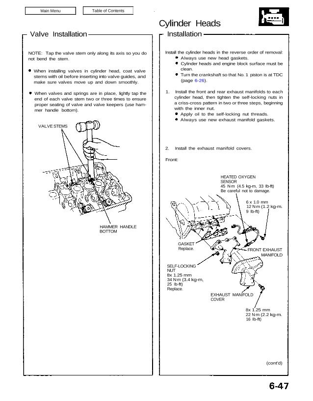
Front:
HEATED OXYGEN
SENSOR
45 N.m (4.5 kg-m, 33 Ib-ft)
Be careful not to damage.
6 x 1.0 mm
12 N.m (1.2 kg-m.
9 Ib-ft)
GASKET
Replace.
SELF-LOCKING
NUT
8x 1.25 mm
34 N.m (3.4 kg-m,
25 Ib-ft)
Replace.
EXHAUST MANIFOLD
COVER
(cont’d)
8x 1.25 mm
22 N.m (2.2 kg-m.
16 Ib-ft)
FRONT EXHAUST
MANIFOLD
Valve Installation
When installing valves in cylinder head, coat valve
stems with oil before inserting into valve guides, and
make sure valves move up and down smoothly.
When valves and springs are in place, lightly tap the
end of each valve stem two or three times to ensure
proper seating of valve and valve keepers (use ham-
mer handle bottom).
VALVE STEMS
HAMMER HANDLE
BOTTOM
NOTE: Tap the valve stem only along its axis so you do
not bend the stem.
Apply oil to the self-locking nut threads.
Always use new exhaust manifold gaskets.
1. Install the front and rear exhaust manifolds to each
cylinder head, then tighten the self-locking nuts in
a criss-cross pattern in two or three steps, beginning
with the inner nut.
Always use new head gaskets.
Cylinder heads and engine block surface must be
clean.
Turn the crankshaft so that No. 1 piston is at TDC
(page 6-26).
Install the cylinder heads in the reverse order of removal:
Cylinder Heads
Installation (cont’d)
Rear:
8 x 1.25 mm
22 N.m (2.2 kg-m,
16 Ib-ft)
HEATED OXYGEN
SENSOR
45 N.m (4.5 kg-m,
33 Ib-ft)
Be careful not to damage.
GASKET
Replace.
REAR EXHAUST
MANIFOLD
EXHAUST
MANIFOLD
COVER
SELF LOCKING NUTS
8 x 1.25 mm
34 N.m (3.4 kg-m,
25 Ib-ft)
Replace.
3. Install the cylinder heads on the engine block.
The cylinder head dowel pins and the head oil con-
trol orifice must be aligned.
CYLINDER HEAD
GASKET (METAL)
Replace.
CYLINDER HEAD
GASKET (METAL)
Replace.
HEAD ORIFICES
DOWEL
PIN
DOWEL PIN
O-RING
Replace.
DOWEL
PINS
CYLINDER HEAD BOLTS
11 x 1.5 mm
78 N.m (7.8 kg-m. 56 Ib-ft)
Apply clean engine oil to the
bolt threads and washer contact
surfaces.
CYLINDER HEAD BOLTS TORQUE SEQUENCE
Specified Torque
11 x 1.5 mm
78 N.m (7.8 kg-m, 56 Ib-ft)
NOTE: We recommend using a beam-type torque
wrench. When using a preset-type torque wrench,
be sure to tighten slowly and not to over-tighten.
Always use a new cylinder head gasket.
Apply clean engine oil to the bolt threads and
washer contact surfaces.
4. Tighten the cylinder head bolts sequentially in two
or three steps.