Categories
Fuel & Emissions

nsxb11003a.pdf

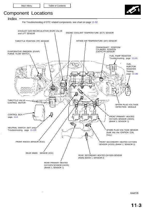
Component Locations Index EXHAUST GAS RECIRCULATION (EGR) VALVE and LIFT SENSOR THROTTLE POSITION (TP) SENSOR EVAPORATIVE EMISSION (EVAP) PURGE FLOW SWITCH ENGINE COOLANT TEMPERATURE (ECT) SENSOR INTAKE AIR TEMPERATURE (IAT) SENSOR CRANKSHAFT POSITION/ CYLINDER POSITION (CKP/CYP) SENSOR FUEL PUMP RESISTER Troubleshooting, page 11-141 FUEL INJECTOR RESISTER Testing, page 11-136 THROTTLE VALVE CONTROL MOTOR CONTROL BOX […]

Categories
Fuel & Emissions

nsxd11028a.pdf

System Description System Connectors [Front Compartment and Under-dash] (cont’d) UNDER-HOOD FUSE/RELAY BOX C464 C249 C446 C425 C439 C412 FLOOR WIRE HARNESS SIDE WIRE HARNESS UNDER-DASH FUSE BOX C405 C406 C404 C318 C458 C228 FRONT COMPARTMENT WIRE HARNESS SUB RELAY BOX A C228 C318 C404 C405 C406 C412 C425 (A/T) C439 C446 C458 C464 NOTE: Several […]

Categories
Automatic Transmission

nsxd14045a.pdf

ATF Cooler The radiator is mounted at the front of the vehicle. The ATF cooler is installed directly on the transmission housing. The ATF is cooled by the engine coolant. OUTLET HOSE INLET HOSE Coolant ATF COOLER Attachments nsxd14045a (134 kB)

Categories
Fuel & Emissions

nsxd11112a.pdf

Fuel Supply System Fuel Injector Resistor Description The fuel injector resistor lowers the current supplied to the fuel injectors to prevent damage to the fuel injector coils. This allows a faster response time of the fuel injectors. ECM PGM-FI MAIN RELAY Testing 1. Disconnect the fuel injector resistor connector. 2. Check for resistance between each […]

Categories
Electrical

nsxd23214a.pdf

Side Marker/Turn Signal/Hazard Flasher System Hazard Warning Switch Removal CAUTION: All SRS wiring harnesses are covered with yellow out- er insulation. Before disconnecting any part of the SRS wire har- ness, Install the short connectors (see page 24-10) Replace the entire affected SRS harness assembly if it ha* an open circuit or damaged wiring. 1. […]

Categories
Automatic Transmission

nsxd14159a.pdf

Gearshift Selector All SRS wiring harnesses are covered with yellow outer insulation. Before disconnecting any part of the SRS wire harness, install the short connectors (see page 23-328). Replace the entire affected SRS harness assembly if it has an open circuit or damaged wiring. CAUTION: SELECT LEVER KNOB 3 N.m (0.3 kg-m, 2 Ib-ft) SRS […]

Categories
Electrical

nsxb23100a.pdf

Charging System Troubleshooting If the charging system light is on, or the battery is dead or low, test the following items in the order listed: 1. Battery (see page 23-68) 2. Charging System Light 3. Alternator/Regulator Charging System Light Test Does the charging system light come on? Start the engine. Does the charging system light […]

Categories
Steering

nsxb17059a.pdf

Illustrated Index CAUTION: Do not try to disassemble the power steering gearbox. If the gearbox is faulty, replace it as an assembly. Corrosion resistant bolt/nut 10 x 97 mm FLANGE BOLT GEARBOX ASSEMBLY STEERING GEARBOX BRACKET CUSHION B Check for damage. 10 x 84 mm FLANGE BOLT 60 N-m (6.0 kg-m, 43 Ib-ft) 10 x […]

Categories
Body

nsxb20021a.pdf

Front and Center Pillar Retainer/Upper Weatherstrip/ Center Pillar Panel Replacement Disassemble in numbered sequence. CAUTION: Wear gloves to remove and install the retainer. NOTE: Check the upper weatherstrip for damage and deterioration, and replace it if necessary. Take care not to bend the front and center pillar retainer. After installing the upper weatherstrip, check for […]

Categories
Cylinder Head & Valve Train

nsxd06025a.pdf

Installation CAUTION: Do not rotate the crankshaft or camshaft without installing the belt. The piston could hit a valve and damage may result. 1 . Install the timing belt in the reverse order of removal; Only keypoints are described here. 2 . Remove all spark plugs. 3. Position the crankshaft and the camshaft pulley as […]