CAUTION: Do not rotate the crankshaft or camshaft
without installing the belt. The piston could hit a valve
and damage may result.
1 . Install the timing belt in the reverse order of removal;
Only keypoints are described here.
2 . Remove all spark plugs.
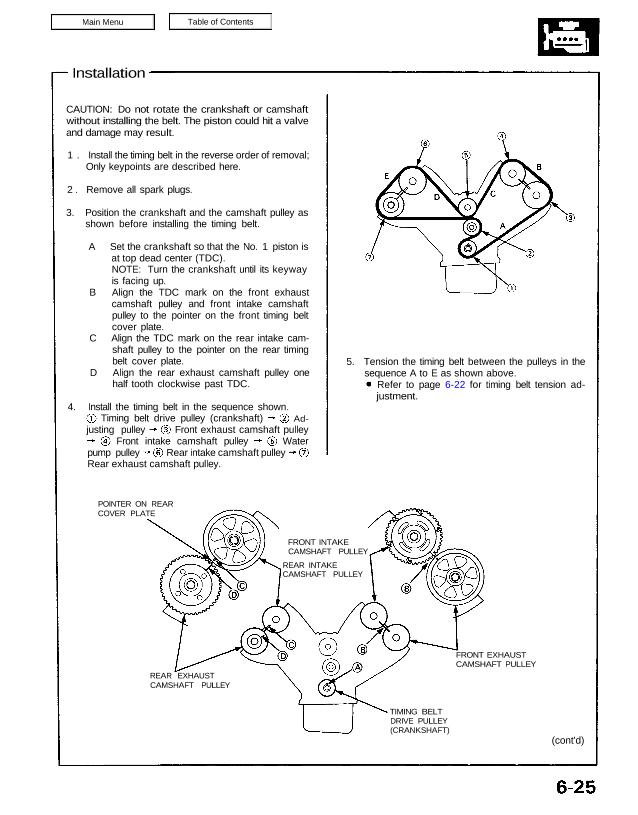
3. Position the crankshaft and the camshaft pulley as
shown before installing the timing belt.
A Set the crankshaft so that the No. 1 piston is
at top dead center (TDC).
NOTE: Turn the crankshaft until its keyway
is facing up.
B Align the TDC mark on the front exhaust
camshaft pulley and front intake camshaft
pulley to the pointer on the front timing belt
cover plate.
C Align the TDC mark on the rear intake cam-
shaft pulley to the pointer on the rear timing
belt cover plate.
D Align the rear exhaust camshaft pulley one
half tooth clockwise past TDC.
POINTER ON REAR
COVER PLATE
REAR EXHAUST
CAMSHAFT PULLEY
TIMING BELT
DRIVE PULLEY
(CRANKSHAFT)
FRONT EXHAUST
CAMSHAFT PULLEY
(cont’d)
5. Tension the timing belt between the pulleys in the
sequence A to E as shown above.
4. Install the timing belt in the sequence shown.
FRONT INTAKE
CAMSHAFT PULLEY
REAR INTAKE
CAMSHAFT PULLEY
Rear exhaust camshaft pulley.
Timing belt drive pulley (crankshaft) Ad-
Water
justing pulley
Front intake camshaft pulley
Front exhaust camshaft pulley
pump pulley Rear intake camshaft pulley
Refer to page 6-22 for timing belt tension ad-
justment.
Prior to installing the cylinder head cover, apply
a thin layer of liquid gasket to the mating surface
of the cylinder head cover and rubber seals to pre-
vent the rubber seal from falling off.
After installation, fill the engine with oil up to the
specified level, run the engine for more than 3
minutes, then check for oil leakage.
8. If the camshaft pulleys are not positioned at TDC,
remove the timing belt and adjust the positioning of
the pulleys, then reinstall the timing belt.
6. Temporarily install the lower cover and crankshaft
pulley.
7. Check the crankshaft pulley and the camshaft
pulleys at TDC.
FRONT:
5.0 mm
PIN PUNCHES
MIDDLE COVER
REAR: TDC MARK
5.0 mm
PIN PUNCHES
Direction
of rotation.
FRONT:
REAR:
TDC MARK
TDC MARK
(White paint)
TDC MARKS
COVER PLATE
TDC MARK
MIDDLE COVER TDC MARKS
Timing Belt
Installation (cont’d)
Refer to page 6-23, 24 for timing belt removal.
Bring the “UP” mark of the camshaft pulleys to
the top, and align the TDC marks on the pulleys.
Align the holes on the camshaft holder pipes to
the camshaft holes, insert 5.0 mm pin punches
and fix them at TDC.
Remove the pin punches after the timing belt has
been reinstalled.
NOTE:
NOTE: