1. Remove the front wheel and bearing unit assembly
(see page 18-15).
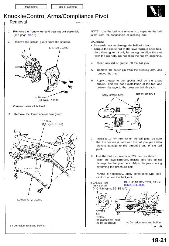
2. Remove the splash guard from the knuckle.
SPLASH GUARD
10 N-m
(1.0 kg-m, 7 Ib-ft)
Corrosion resistant bolt/nut
3. Remove the lower control arm guard.
10 N-m
(1.0 kg-m, 7 Ib-ft)
LOWER ARM GUARD
Corrosion resistant bolt/nut
NOTE: Use the ball joint removers to separate the ball
joints from the suspension or steering arm.
CAUTION:
• Be careful not to damage the ball joint boot.
• Torque the castle nut to the lower torque specifica-
tion, then tighten it only far enough to align the slot
with the pin hole. Do not align the nut by loosening.
4. Clean any dirt or grease off the ball joint.
5. Remove the cotter pin from the steering arm, and
remove the nut.
6. Apply grease to the special tool on the areas
shown. This will ease installation of the tool and
prevent damage to the pressure bolt threads.
Apply grease here. PRESSURE BOLT
7. Install a 12 mm hex nut on the ball joint. Be sure
that the hex nut is flush with the ball joint pin end to
prevent damage to the threaded end of the ball
joint.
8. Use the ball joint remover, 28 mm, as shown.
Insert the jaws carefully, making sure you do not
damage the ball joint boot. Adjust the jaw spacing
by turning the pressure bolt.
NOTE: If necessary, apply penetrating type lubri-
cant to loosen the ball joint.
CASTLE NUT
40-48 N-m
BALL JOINT REMOVER, 28 mm
07MAC-SL00200
(4.0-4.8 kg-m, 29-35 Ib-ft)
COTTER
PIN
Replace.
On reassembly, bend
the pin as shown. Corrosion resistant bolt/nut
Knuckle/Control Arms/Compliance Pivot
Knuckle/Control Arms/Compliance Pivot
Removal
9. Once the tool is in place, turn the adjusting bolt as
necessary to make the jaws parallel. Then hand-
tighten the pressure bolt, and recheck the jaws to
make sure they are still parallel.
PRESSURE BOLT
ADJUSTING BOLT
10. With a wrench, tighten the pressure bolt until the
ball joint shaft pops loose from the steering arm.
Wear eye protection. The ball joint
can break loose suddenly and scatter dirt or other
debris in your eyes.
11. Remove the tool, then remove the nut from the end
of the ball joint and pull the ball joint out of the
steering/suspension arm. Inspect the ball joint boot,
and replace it if damaged.
12. Remove the cotter pin and lower control arm ball
joint nut.
13. Install the 12 mm hex nut on the ball joint. Be sure
that the 12 mm hex nut is flush with the ball joint
pin end, or the threaded section of the ball joint pin
might be damaged by the ball joint remover.
14. Use the ball joint remover, 32 mm, as shown on page
18-21 to separate the ball joint and lower control
arm.
NOTE: If necessary, apply penetrating type lubri-
cant to loosen the ball joint.
CASTLE NUT
12 x 1.25 mm
55-65 N-m
(5.5-6.5 kg-m, 40-47 Ib-ft)
COTTER BALL JOINT
PIN REMOVER, 32 mm
Replace. 07MAC – SL00100
On reassembly,
bend the cotter pin as shown.
Corrosion resistant bolt/nut
1 5. Remove the cotter pin and the upper ball joint nut.
16. Install the 12 mm hex nut on the ball joint. Be sure
that the 12 mm hex nut is flush with the ball joint
pin end, or the threaded section of the ball joint pin
might be damaged by the ball joint remover.
17. Use the ball joint remover, 32 mm, as shown on page
18-21 to separate the ball joint and upper arm.
NOTE: If necessary, apply penetrating type lubri-
cant to loosen the ball joint.
BALL JOINT REMOVER, 32 mm
07MAC – SL00100
COTTER PIN
Replace.
On reassembly, bend the
cotter pin as shown.
CASTLE NUT
12 x 1.25 mm
55-65 N-m
(5.5-6.5 kg-m,
40-47 Ib-ft)
Corrosion resistant bolt/nut
18. Remove the knuckle.
KNUCKLE
19. Separate the lower control arm and damper by
removing the damper mounting bolt.
DAMPER
MOUNTING
BOLT
Corrosion resistant bolt/nut
SELF-LOCKING NUT
12 x 1.25 mm
Replace.
95 N-m (9.5 kg-m, 69 Ib-ft)
20. Hold the ball pin of the stabilizer link with a hex
wrench, and loosen the self-locking nut.
STABILIZER
LINK
LOWER CONTROL
ARM
HEX WRENCH
SELF-LOCKING NUT
12 x 1.25 mm
Replace.
85 N-m (8.5 kg-m, 61 Ib-ft)
Corrosion resistant bolt/nut
21. Disconnect the stabilizer link from the lower control
arm.
Knuckle/Control Arms/Compliance Pivot
Removal
22. Remove the cotter pin and lower arm ball joint nut.
23. Install the 12 mm hex nut on the ball joint. Be sure
that the 12 mm hex nut is flush with the ball joint
pin end, or the threaded section of the ball joint pin
might be damaged by the ball joint remover.
24. Use the ball joint remover, 32 mm, as shown on page
18-21 to separate the ball joint and compliance pivot.
NOTE: If necessary, apply penetrating type lubri-
cant to loosen the ball joint.
CAUTION: Avoid damaging the ball joint boot.
CASTLE NUT
12 x 1.25 mm
55-65 N-m
(5.5-6.5 kg-m, 40-47 Ib-ft)
COTTER
PIN
Replace.
On reassembly,
bend the cotter pin
as shown.
BALL JOINT REMOVER, 32 mm
07MAC-SL00100
Corrosion resistant bolt/nut
25. Remove the lower control arm by removing the ad-
justing bolt.
SELF-LOCKING NUT
12 x 1.25 mm
Replace.
125 N-m
(12.5 kg-m, 90 Ib-ft)
ADJUSTING
BOLT
ADJUSTING CAM
LOWER CONTROL ARM
Corrosion resistant bolt/nut
26. Remove the cotter pin and upper arm ball joint nut.
27. Install the 12 mm hex nut on the ball joint. Be sure
that the 12 mm hex nut is flush with the ball joint
pin end, or the threaded section of the ball joint pin
might be damaged by the ball joint remover.
28. Use the ball joint remover, 32 mm, as shown on page
18-21 to separate the ball joint and compliance pivot.
NOTE: If necessary, apply penetrating type lubri-
cant to loosen the ball joint.
CAUTION: Avoid damaging the ball joint boot.
CASTLE NUT
12 x 1.25 mm
55-65 N-m
(5.5-6.5 kg-m, 40-47 Ib-ft)
BALL JOINT REMOVER, 32 mm
07MAC-SL00100
Corrosion resistant bolt/nut
COTTER PIN
Replace.
On reassembly,
bend the cotter
pin as shown.
29. Remove the stabilizer bar bracket from the com-
pliance pivot.
30. Remove the three lower compliance pivot bolts.
STABILIZER
BAR
COMPLIANCE PIVOT
ASSEMBLY
FLANGE BOLT
8 x 1.25 mm
22 N-m
(2.2 kg-m, 16 Ib-ft)
FLANGE BOLT
12 x 1.25 mm
95 N-m
(9.5 kg-m, 69 Ib-ft)
Corrosion resistant bolt/nut
31. Remove the compliance pivot assembly by remov-
ing the bolts and nuts shown.
32. Remove the upper control arm assembly by remov-
ing the flange bolt shown.
SELF-LOCKING
NUTS
12 x 1.25 mm
Replace.
95 N-m
(9.5 kg-m, 69 Ib-ft)
FLANGE BOLT
10 x 1.25 mm
60 N-m
(6.0 kg-m, 43 Ib-ft)
FLANGE BOLTS
10 x 1.25 mm
60 N-m
(6.0 kg-m, 43 Ib-ft)
Corrosion resistant bolt/nut
NOTE:
• Install the upper control arm on the frame before
installing the compliance pivot assembly.
• Install the compliance pivot bolts and nuts. Tor-
que them to the specified torque in the order.
1. Loosely tighten the flange bolt
2. Insert the stud bolts into the frame.
3. Install the three flange bolts and tighten to the
specified torque.
4. Install the two flange bolts and tighten to the
specified torque.
5. Tighten the flange bolt
6. Install the 12 mm self-locking nuts and tighten
to the specified torque.
STUD BOLT
FLANGE BOLTS
10 x 1.25 mm
60 N-m
(6.0 kg-m, 43 Ib-ft)
FLANGE BOLTS
12 x 1.25 mm
95 N-m
(9.5 kg-m, 69 Ib-ft)
SELF-LOCKING
NUTS
12 x 1.25 mm
Replace.
95 N-m
(9.5 kg-m, 69 Ib-ft)
UPPER CONTROL
ARM
FLANGE BOLT
12 x 1.25 mm
95 N-m
(9.5 kg-m, 69 Ib-ft)
Corrosion resistant
bolt/nut
COMPLIANCE
PIVOT ASSEMBLY