Categories
Electrical

nsxb23235a.pdf

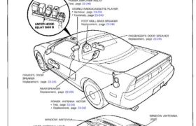
Stereo Sound System Component Location Index SRS components are located in this area. Review the SRS component locations, precautions, and procedures in the SRS section 24 before performing repairs or ser- vice. POWER AMPLIFIER RELAY Test, page 23-240 STEREO RADIO/CASSETTE PLAYER Removal, page 23-238 Terminals, page 23-240 FOOT WELL BASS SPEAKER Replacement, page 23-245 PASSENGER’S […]

Categories
Electrical

nsxb23267a.pdf

Passenger’s Door Actuator Test – 1. Remove the door panel (see section 20). 2. Disconnect the 8-P connector from the actuator. View from wide side ACTUATOR 3. Test actuator operation: LOCK: With battery power connected to the No. 7 terminal, connect ground to the No. 8 terminal momentarily. UNLOCK: With battery power connected to the […]

Categories
Differential

nsxb15017a.pdf

Differential Illustrated Index NOTE: If the parts marked with an asterisk (*) ere replaced, the bearing preload must be adjusted (see page 15-26 parts marked with * 76 mm THRUST SHIM Selection, Adjustment, page 15-27 * TAPERED ROLLER BEARING Replacement, page 15-19 Inspect for operation. FINAL DRIVEN GEAR Inspect for wear and damage. CLUTCH DISC […]

Categories
Fuel & Emissions

nsxb11141a.pdf

Fuel Pump Resistor Troubleshooting Flowchart — Engine will not start. — Inspection of fuel pump resis- tor. Check the operation of the PGM- FI main relay: 1. Disconnect the fuel pump resistor 2P connector. 2. Measure voltage between fuel pump resistor connector ter- minal No. 2 and body ground when the ignition switch is first […]

Categories
Driveshafts

nsxb16012a.pdf

Intermediate Shaft Replacement 1. Drain the oil from the transmission (see section 13 M/T or section 14 A/T). 2. Remove the right driveshaft assembly (see page 16-3). 3. Remove the heat shield. Corrosion resistant bolt/nut FLANGE BOLT 6 x 1.0 mm 10 N-m (1.0 kg-m, 7 Ib-ft) HEAT SHIELD 4. The bearing support assembly is […]

Categories
Steering

nsxd17015a.pdf

Installation CAUTION: All SRS wiring harnesses are covered with yellow outer insulation. Replace the entire affected SRS harness assembly if it has an open circuit or damaged wiring. 1. Slip the lower end of the steering joint onto the pin- ion shaft. 2. Reposition the column assembly on the hanger bracket and loosely tighten with […]

Categories
Cylinder Head & Valve Train

nsxb06009a.pdf

Valve Clearance Adjustment NOTE: Valves should be adjusted cold, when the cylinder head temperature is less than 100°F (38°C). Adjustment is the same for both intake and exhaust valves. Adjust valve clearance at TDC of each cylinder. Do not rotate the engine counterclockwise. The tim- ing belt could jump a tooth on the camshaft pulleys. […]

Categories
Fuel & Emissions

nsxb11010a.pdf

System Descriptions Electrical Connections Main Menu Table of Contents System Descriptions Electrical Connections IGNITION PGM-FI MAIN RELAY FUEL PUMP RESISTOR SWITCH CKPI CYP SENSOR INJECTORS BS CVP 1P B14 CYP 1M B7 CKP ZP B15 CKP 2M 88 CKP 1F B16 CKP 1M 85 CYP 2P B13 CYP 2M INJ1 A1 ⇀↼↴∣↸⇃↲⋜ A2 INJ3 A3 […]

Categories
Suspension

nsxb18003a.pdf

Component Locations Index Front Suspension: FRONT DAMPER Removal, page 18-27 Disassembly/Inspection, page 18-27 Reassembly, page 18-29 Installation, page 18-29 Disposal . . . . . . . . . 18-44 FRONT SUSPENSION ASSEMBLY • Knuckle/Control Arms/ Compliance Pivot Removal, page 18-21 • Illustrated Index, page 18-20 • Ball Joint Boot Replacement, page 18-26 FRONT HUB […]

Categories
Heating, Ventilation and Air Conditioning

nsxb22008a.pdf

Description Fan Control Unit The fan control unit performs calculations based on signals from the radiator fan control sensor. It them controls the operation of radiator fan speed (High-Low), engine compartment fan, condenser fan and A/C compressor. IG2 RADIATOR FAN (Low) RADIATOR FAN CONTROL SENSOR RADIATOR FAN (High) ENGINE COMPARTMENT FAN CONDENSER FAN (Right and […]