Categories
Automatic Transmission

nsxd14137a.pdf

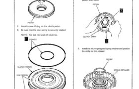
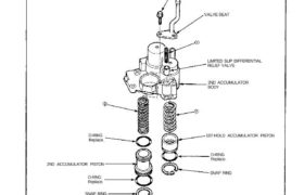
(cont’d) RETURN SPRING O-RING SPRING RETAINER CIRCLIP DISC SPRING CLUTCH PISTON 5. Install the return spring and spring retainer and position the circlip on the retainer. CLUTCH DRUM O-RINGS PISTON 2. Install a new O-ring on the clutch piston. 3. Be sure that the disc spring is securely staked. NOTE: For 1st, 3rd and 4th […]

Categories
Manual Transmission

nsxb13016b.pdf

Mainshaft, Countershaft, Differential Assemblies Removal 1. Remove the change holder assembly from the clutch housing. CLUTCH HOUSING CHANGE HOLDER ASSEMBLY 2. Remove the mainshaft assembly and countershaft assembly with the shift fork from the clutch housing. NOTE: Tape the mainshaft splines to protect them before removing the mainshaft and countershaft assemblies. MAINSHAFT ASSEMBLY COUNTERSHAFTASSEMBLY SHIFT […]

Categories
Automatic Transmission

nsxd14152a.pdf

Torque Converter Disassembly 6 x 1.0 mm 12 N.m(1.2 Kg-m. 9 Ib-ft) DRIVE PLATE Inspect for cracks. RING GEAR/TORQUE CONVERTER ASSEMBLY WASHER 12 x 1.0mm 75 N.m (7.5 Kg-m, 54 Ib-ft) Torque in crisscross pattern. O-RING Replace. Attachments nsxd14152a (143 kB)

Categories
Electrical

nsxb23244a.pdf

Stereo Sound System Antenna Tube Replacement 1. Remove the antenna mast (see page 23-242). 2. Remove the power antenna motor (see page 23-242). 3. Remove the retaining screw, and pull the antenna tube out of its socket in the drive housing. ANTENNA TUBE RETAINING SCREW 4. Remove the plastic guide and plastic insulator tube, and […]

Categories
Body

nsxb20006a.pdf

Doors REAR SASH Adjustment, see page 20-17(’93-’96),16(’91-’92) REAR GLASS GUIDE Index FRONT GLASS GUIDE REGULATOR ASSEMBLY INNER MOLDING STOPPER PLATES GLASS Adjustment, see page 20-14(’93-’96), 13(’91-’92) FRONT SASH Adjustment, see page 20-17(’93-’96), 16(’91-’92) POWER MIRROR INSIDE STABILIZERS OUTER MOLDING DOOR HINGEPOWER WINDOW MOTOR LOCK CYLINDER DOOR Disassembly, see page 20-7 (’93-’96),6(’91-’92) Assembly, see page 20-13 […]

Categories
Electrical

nsxb23185a.pdf

Retractor Switch Test 1. Remove the retractor switch (see previous page). 2. Check for continuity between the terminals in each switch position according to the table. Retractor Switch RETRACTOR SWITCH Retractor Switch Retractor Switch Light Bulb Replacement 1. Remove the retractor switch (see previous page). 2. Turn the bulb 45° counterclockwise to remove it. RETRACTOR […]

Categories
Heating, Ventilation and Air Conditioning

nsxb22080a.pdf

Condenser Overhaul 1. Remove the four bolts and nuts. Then separate the condenser duct from the condenser shroud, and remove the condenser. 2. Remove the three mounting screws, then remove the condenser fan from the condenser shroud. CONDENSER New parts (R-134a) CONDENSER DUCT NUTS 6 x 1.0 mm 10 N-m (1.0 kg-m, 7 Ib-ft) SPACER […]

Categories
Automatic Transmission

nsxd14122a.pdf

SPRING SPECIFICATIONS SNAP RING SNAP RING Unit of length: mm (in) O-RING Replace. 1ST-HOLD ACCUMULATOR PISTON O-RING Replace. 2ND ACCUMULATOR PISTON O-RING Replace. 2ND ACCUMULATOR BODY LIMITED SLIP DIFFERENTIAL RELIEF VALVE VALVE SEAT 6 x 1.0 mm 12N.m (1.2 kg-m, 9 Ib-ft) Clean all parts thoroughly in solvent or carburetor cleaner, and dry with compressed […]

Categories
Electrical

nsxb23254a.pdf

Trunk Opener Opener Switch Test 1. Remove the driver’s door panel, then push the switch out of the door panel as shown. 2. Check for continuity between the terminals. • There should be continuity between the A and B terminals when the switch is pushed. • There should be no continuity when the switch is […]

Categories
Fuel & Emissions

nsxd11115a.pdf

Fuel Pump Description Because of its compact impeller design, the fuel pump is installed inside the fuel tank, thereby saving space and simplify- ing the fuel line system. FUEL PUMP FUEL PUMP BRACKET FUEL FILTER FUEL PUMP CROSS SECTION (Side view) RELIEF VALVE FEUL PUMP COVER FUEL PUMP ASSEMBLY CROSS SECTION (Top view) DISCHARGE PORT […]