RETURN SPRING
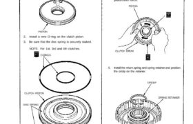
O-RING
SPRING RETAINER
CIRCLIP
DISC SPRING
CLUTCH PISTON
5. Install the return spring and spring retainer and position
the circlip on the retainer.
CLUTCH DRUM
O-RINGS
PISTON
2. Install a new O-ring on the clutch piston.
3. Be sure that the disc spring is securely staked.
NOTE: For 1st, 3rd and 4th clutches.
PISTON
CAUTION: Do not pinch O-ring by installing the
piston with force.
4. Install the piston in the clutch drum. Apply pressure
and rotate to ensure proper seating.
NOTE: Lubricate the piston O-ring with ATF before in-
stalling.
Reassembly
NOTE:
Clean all parts thoroughly in solvent or carburetor clean-
er, and dry with compressed air.
Blow out all passages.
Lubricate all parts with ATF before assembly.
1. Inspect for a loose check valve.
CHECK VALVE
9. Remove the special tools.
Do not set here.Set here.
8. Install the circlip.
CAUTION: If either end of the compressor attach-
ment is set over an area of the spring retainer
which is unsupported by the retainer spring, the re-
tainer may be damaged.
CLUTCH SPRING
COMPRESSOR
BOLT ASSEMBLY
07GAE–PG40200
CLUTCH SPRING
COMPRESSOR
ATTACHMENT
07HAE–PL50100
7. Compress the clutch return spring.
CLUTCH SPRING
COMPRESSOR
ATTACHMENT
07LAE–PX40100
6. Install the special tools as shown.
Reassembly (cont’d)
Clutch
(cont’d)
CLUTCH DISC
CLUTCH END PLATE
11. Soak the clutch discs thoroughly in ATF for a minimum
of 30 minutes.
12. Starting with a clutch plate, alternately install the
clutch plates and discs. Install the clutch end plate
with flat side toward the disc.
NOTE: Before installing the plates and discs, make
sure the inside of the clutch drum is free of dirt or other
foreign matter.
SNAP RINGInstall in this
direction.
SCREWDRIVER
13. Install the snap ring10. Install the disc spring.
DISC SPRING
NOTE:
For 1st-hold and 2nd clutches
Install the disc spring in the direction shown.
Clutch
Reassembly (cont’d)
14. Measure the clearance between the clutch end plate
and top disc with a dial indicator. Zero the dial indicator
with the clutch end plate lowered and lift it up to the
snap ring. The distance that the clutch end plate
moves is the clearance between the clutch end plate
and top disc.
NOTE: Measure at three locations.
End Plate-to-Top Disc Clearance:
15. If the clearance is not within the service limits, select a
new clutch end plate from the following table.
NOTE: If the thickest clutch end plate is installed but
the clearance is still over the standard, replace the
clutch discs and clutch plates.
2ND, 3RD, 4TH and 1ST HOLD CLUTCH
END PLATE TOP DISC
1ST CLUTCH
PLATE NUMBER Thickness
END PLATE