Categories
Automatic Transmission

nsxd14109a.pdf

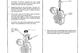
7. Remove the valve and thoroughly clean it and the valve body with solvent. Dry all parts with compressed air, then reassemble using ATF as a lubricant. VALVE BODY VALVE ATF-soaked #600 abrasive paper Repair NOTE: This repair is only necessary if one or more of the valves in a valve body do not slide […]

Categories
Fuel & Emissions

nsxe11076a.pdf

Idle Control System Troubleshooting Flowchart A/T Shift Position Signal This signals the PGM-FI ECU when the transmission is in Neutral or Park. Inspection of A/T Shift Position Signal. Turn the ignition switch ON. Observe the A/T shift indicator and select each position separately. See A/T Shift Position Indicator Inspection.Does the indicator light properly? Turn the […]

Categories
Electrical

nsxd23091a.pdf

Ignition Timing Inspection and Setting 1. Start the engine and allow it to warm up (radiator fan comes on). 2. Pull out the service check connector located under the middle of the dash. Connector the BLU and GRN/WHT terminals with a jumper wire (see sec- tion 11). 3. Check the idle speed (see page 23-92). […]

Categories
Body

nsxb20036a.pdf

Rear Hatch Glass Molding Replacement CAUTION: • Wear gloves to replace the molding. • Do not damage the glass and defroster grid lines. 2. Place the rear hatch assembly on its surface as shown. CAUTION: Avoid setting the glass on its edges; small chips may later develop into cracks. 3. With a helper holding the […]

Categories
Fuel & Emissions

nsxd11122a.pdf

Fuel Supply System PGM-FI Main Relay (cont’d) Troubleshooting Flowchart (To page 11-123) BLK/ WHT GRN/ YEL/ BLK PGM-FI MAIN RELAY BLK/ YELBLK YEL/ BLU BLK/ YEL BLK/ YEL BLK Engine will not start. Inspection of PGM-FI main relay. Disconnect the PGM-FI main relay connectors. Check for continuity between BLK terminal and body ground. Does continuity […]

Categories
Fuel & Emissions

nsxb11144a.pdf

Fuel Supply System PGM-FI Main Relay Troubleshooting Is there continuity? Check for an open or short in the wire: Measure voltage between the PGM-FI main relay 4P connector terminal No. 3 and body ground. Is there battery voltage? Check for an open or short in the wire: 1. Turn the ignition switch ON (II). 2. […]

Categories
Fuel & Emissions

nsxb11153a.pdf

Fuel Injection Air (FIA) Control System Description The Fuel Injection Air (FIA) Control system enables fresh air to be drawn through the throttle body and fuel injector port. IDLE ADJUSTING SCREW THROTTLE BODY FUEL INJECTOR AIR FLOW Attachments nsxb11153a (56 kB)

Categories
Fuel & Emissions

nsxb11159a.pdf

Three Way Catalytic Converter (TWC) Description The Three Way Catalytic Converter (TWC) is used to convert hydrocarbons (HC), carbon monoxide (CO), and oxides of nitrogen (NOx) in the exhaust gas to carbon dioxide (CO2), dinitrogen (Nz) and water vapor. SECONDARY HEATED OXYGEN SENSOR (SENSOR 2) THREE WAY CATALYST HOUSING Attachments nsxb11159a (52 kB)

Categories
Electrical

nsxb23128a.pdf

Gauge Assembly Bulb Locations GAUGE LIGHTS (1.4W x 2) SRS INDICATOR LIGHT (1.4 W) RIGHT TURN SIGNAL INDICATOR LIGHT (1.4 W) EPS INDICATOR LIGHT (1.4 W) BRAKE SYSTEM LIGHT (1.4 W) SEAT BELT REMINDER LIGHT (1.4 W) TCS INDICATOR LIGHT (1.96 W) LOW FUEL INDICATOR LIGHT (1.4 W) GAUGE LIGHT (1.4 W) HIGH BEAM INDICATOR […]

Categories
Electrical

nsxb23118a.pdf

Radiator and Condenser Fan Controls Engine Compartment Fan Motor Test (A/T) 1. Disconnect the 2-P connector from the engine compartment fan motor. 2. Test the motor by connecting battery power to the A terminal, and ground to the B terminal. 3. If the motor fails to run or does not run smoothly, replace it. Engine […]