Ignition Timing Inspection and Setting
1. Start the engine and allow it to warm up (radiator
fan comes on).
2. Pull out the service check connector located under
the middle of the dash. Connector the BLU and
GRN/WHT terminals with a jumper wire (see sec-
tion 11).
3. Check the idle speed (see page 23-92).
4. Connect a timing light to the service loop; while the
engine idles, point the light toward the pointer on
the timing belt cover.
SERVICE LOOP
TIMING LIGHT
5. If necessary, adjust ignition timing to the following
specifications:
Ignition Timing: 15° ±2° BTDC (RED mark)
Idle Speed (rpm):
NOTE: All electrical systems turned OFF.
POINTER
RED MARK
CRANKSHAFT PULLEY
WHITE MARK
6. If necessary, adjust the ignition timing, adjust by
turning the adjusting screw on the ignition timing
adjuster in the control box.
Remove the control box cover.
7. Remove the jumper wire from the service check
connector.
8. After adjusting, reinstall the cover on the ignition
timing adjuster with new rivets.
ADJUSTING SCREW
To ADVANCETo RETARD
Reconnect the adjuster to the car, start the
engine, and turn the adjusting screw
counterclockwise to retard the timing, or
clockwise to advance it, as necessary.
CAUTION: Do not damage the adjuster when
removing the rivets.
Remove the ignition timing adjuster from the
control box.
Drill the two rivets off with a 3/16 in. drill bit,
then separate the cover from the adjuster.
3-P CONNECTOR
CONTROL BOXIGNITION TIMING
ADJUSTER
Remove the two screws from the control box
then disconnect the 3-P connector from the igni-
tion timing adjuster.
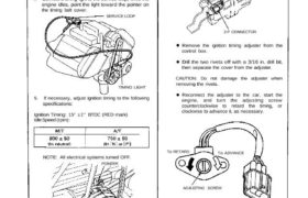