Idle Control System
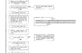
Troubleshooting Flowchart A/T Shift Position Signal
This signals the PGM-FI ECU when the transmission is in Neutral or Park.
Inspection of A/T Shift Position
Signal.
Turn the ignition switch ON.
Observe the A/T shift indicator and
select each position separately.
See A/T Shift Position Indicator
Inspection.Does the indicator light properly?
Turn the ignition switch OFF.
Connect the ECU test harness
between the ECU and connector.
Disconnect “B” connector from
the engine wire harness only, not
the ECU (page 11-21).
10V
B7
A26
Turn the ignition switch ON.
Measure voltage between B7
( + ) terminal and A26 (-) ter-
minal.
Is there approx. 10 V?
Substitute a known-good ECU
and recheck. If prescribed voltage
is now available, replace the
original ECU.
Turn the ignition switch OFF.
Reconnect “B” connector to the
engine wire harness.
Turn the ignition switch ON.
(To page 11-77)
(From page 11-76)
Less than 1 V
B7
A26
Measure voltage between B7
( + ) terminal and A26 (-) ter-
minal with the transmission in
Is there less than 1 V?
Repair open in LT GRN wire
between ECU (B7) and gauge
assembly.
Repair open in GRN wire be-
tween the gauge assembly
and shift position console
switch.
Measure voltage between B7
( + ) terminal and A26 (-) ter-
minal with the transmission in
Less than 1 V
B7
A26
Is there less than 1 V?
Repair open in GRN/WHT wire
between gauge assembly and
shift position console switch.
Measure voltage between B7
( + ) terminal and A26 (-) ter-
minal with the transmission in
gear.
Repair short in LT GRN wire bet-
ween ECU (B7) and gauge
assembly.
Is there approx. 10V?
A/T shift position signal is OK.