Categories
Heating, Ventilation and Air Conditioning

nsxb22091a.pdf

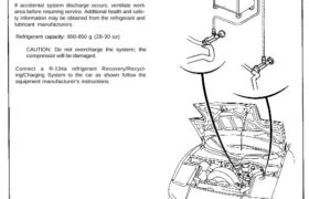
Charging Only use service equipment that is U.L.-listed and is certified to meet the requirements of SAE J2210 to remove HFC-134a (R-134a) from the air conditioner system. CAUTION: Exposure to air conditioner refrigerant and lubricant vapor or mist can irritate eyes, nose and throat. Avoid breathing the air conditioner refrigerant and lubricant vapor or mist. […]

Categories
Heating, Ventilation and Air Conditioning

nsxb22081a.pdf

Compressor Description This compressor is a Nippondenso piston type for R-134a. A revolving inclined disc drives the surrounding 10 reciprocating pistons. As the inclined disc revolved, it pushes the pistons, protected by a ceramic shoe, thus compress- ing the refrigerant. RELIFE VALVE PISTONS FIELD COIL Attachments nsxb22081a (49 kB)

Categories
Fuel & Emissions

nsxd11136a.pdf

Intake Air System Description Satisfactory power performance is achieved by closing and opening the intake air bypass (IAB) control valves. High tor- que at low engine speed is achieved when the valves are closed, whereas high power at high engine speed is achieved when the valves are opened. Intake Air Bypass (IAB) Control System OPEN: […]

Categories
Differential

nsxb15018a.pdf

Preset Torque Inspection On-Car: 1. Lift up right rear wheel, and place the safety stand. (Lift and Support Points, see section 1). 2. Block the other three wheels. 3. Measure preset torque clockwise using a torque wrench as shown. Standard: 60–140 N·m (6–14 kg-m, 43–101 Ib-ft) Service Limits: 30 N·m (3 kg-m, 22 Ib-ft) TORQUE […]

Categories
Fuel & Emissions

nsxd11152a.pdf

Emission Control System Description The evaporative emission controls are designed to minimize the amount of fuel vapor escaping to the atmosphere. The system consists of the following components: A. Evaporative Emission (EVAP) Control Canister An EVAP control canister is used for the temporary storage of fuel vapor until the fuel vapor can be purged from […]

Categories
Fuel & Emissions

nsxd11120a.pdf

Fuel Supply System Description The PGM-FI main relay actually contains two individual relays. The relay is located behind the passenger’s seat back panel. One relay is energized whenever the ignition is on which supplies the battery voltage to the ECM, power to the fuel injectors, and power for the second relay. The second relay is […]

Categories
Fuel & Emissions

nsxe11104a.pdf

Fuel Supply System Main Relay (cont’d) Troubleshooting Flowchart Engine will not start. Inspection of main relay. Disconnect the main relay con- nectors. Measure the voltage between YEL/BLU terminal and body ground. Is there battery voltage? Replace ACG fuse. Turn the ignition switch ON. Measure the voltage between BLK/YEL terminal and body ground. Replace No. 2 […]

Categories
Brakes & ABS

nsxe19069a.pdf

Bleeding Air Bleeding with ALB Checker 1. Disconnect the 6-P inspection connecotor (PNK) from the connector cover located under the glove box and connect the inspection connector to the ALB checker. ANTI-LOCK BRAKE SYSTEM INDICATOR LIGHT CONNECTOR COVER ALB CHECKER 07HAJ – SG00100 or 07HAJ – SG0010B (US) or 07HAJ-SG00200 (Canada) 6-P INSPECTION CONNECTOR CAUTION: […]

Categories
Fuel & Emissions

nsxb11121a.pdf

Inspection of A/T Gear Position Signal. This signals the ECM when the transmission is in position. Automatic Transaxle (A/T) Gear Position Signal Check the operation of the A/T gear position switch: 1. Turn the ignition switch ON (II). 2. Observe the A/T shift position indicator and select each posi- tion separately. Does the indicator light […]

Categories
Differential

nsxb15022a.pdf

I Clutch Disc, Clutch Plate Replacement NOTE: The clutch discs and clutch plates should be replaced as a set. 1. Remove the clutch discs and clutch plates (see page15-20). 2. Soak the clutch discs for five minutes in transmis- sion oil. 3. Install the clutch discs, clutch plates, and a stan- dard shim. NOTE: Position […]