Main Relay (cont’d)
Troubleshooting Flowchart
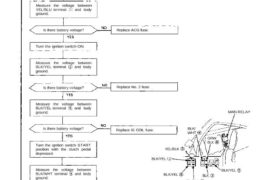
Engine will not start.
Inspection of main relay.
Disconnect the main relay con-
nectors.
Measure the voltage between
YEL/BLU terminal and body
ground.
Is there battery voltage? Replace ACG fuse.
Turn the ignition switch ON.
Measure the voltage between
BLK/YEL terminal and body
ground.
Replace No. 2 fuse.Is there battery voltage?
Measure the voltage between
BLK/YEL terminal and body
ground.
Is there battery voltage? Replace IG COIL fuse.
MAIN RELAY
BLK/
WHT
GRW
BLK
YEL/BLK
BLK/YEL
BLK/YEL
YEL/BLU
BLK
BLK/YEL
Turn the ignition switch START
position with the clutch pedal
depressed.
Measure the voltage between
BLK/WHT terminal and body
ground.
Is there battery voltage? Replace No. 7 fuse.
(To page 11-105)
(From page 11-104)
Turn the ignition switch off.
Connect the ECU test harness
between the ECU and connector.
Disconnect “A” connector from
the ECU only, not the main wire
harness (page 11-21).
Check for continuity between
GRN/BLK terminal and A7 ter-
minal.
Does continuity exist?
Repair open in GRN/BLK wire
between ECU (A7) and Main
Relay.
battety voltage?
A23 A25Reconnect “A” connector to the
ECU. Reconnect the main relay.
Turn the ignition switch ON.
Measure the voltage between
A25 (+) terminal and A23 (-) ter-
minal.
Is there battery voltage?
Turn the ignition switch OFF.
Replace main relay.
1V or less
A7 A23
Measure the voltage between A7
(+) terminal and A23 (-) terminal
when the ignition switch is first
turned ON.
Is there 1V or less?
(for 2 seconds)
Replace main relay.
Substitute a known-good ECU
and recheck. If prescribed
voltage is now available, replace
the original ECU.