Fuel Supply System
Description
The PGM-FI main relay actually contains two individual
relays.
The relay is located behind the passenger’s seat back
panel.
One relay is energized whenever the ignition is on which
supplies the battery voltage to the ECM, power to the
fuel injectors, and power for the second relay.
The second relay is energized for 2 seconds when the
ignition is switched on, and when the engine is running
which supplies power to the fuel pump.
Relay Testing
NOTE: If the car starts and continues to run, the
PGM-FI main relay is OK.
1. Remove the PGM-FI main relay.
2. Attach the battery positive terminal to the No. 4
terminal and the battery negative terminal to the
No. 8 terminal of the PGM-FI main relay. Then
check for continuity between the No. 5 terminal
and No. 7 terminal of the PGM-FI main relay.
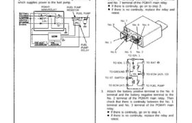
3. Attach the battery positive terminal to the No. 6
terminal and the battery negative terminal to the
No. 2 terminal of the PGM-FI main relay. Then
check that there is continuity between the No. 1
terminal and No. 3 terminal of the PGM-FI main
relay.
FUEL
PUMP
RELAY
FUEL PUMP
RESISTOR
FUEL PUMP
PGM-FI
MAIN RELAY
No. 3
No. 7
No. 8 No. 4
No. 1
No. 6 No. 5 No. 2
TO IGN. 1
TO BATTO IGN. 1
TO GROUND
TO ST. SWITCH
TO ECM (A7)
TO ECM (A25. CD
TO FUEL PUMP
PGM-FI Main Relay
If there is continuity, go on to step 4.
If there is no continuity, replace the relay and
retest.
4. Attach the battery positive terminal to the No. 3
terminal and battery negative terminal to the No. 8
terminal of the PGM-FI main relay. Then check that
there is continuity of the PGM-FI main relay. Then
check that there is continuity between the No. 5
terminal and No. 7 terminal of the PGM-FI main
relay.
If there is continuity, the relay is OK;
If the fuel pump still does not work, go to
Harness Testing in the next column.
If there is no continuity, replace the relay and
retest. (cont’d)
If there is continuity, go on to step 3.
If there is no continuity, replace the relay and
retest.
Description
The PGM-FI main relay actually contains two individual
relays.
The relay is located behind the passenger’s seat back
panel.
One relay is energized whenever the ignition is on which
supplies the battery voltage to the ECM, power to the
fuel injectors, and power for the second relay.
The second relay is energized for 2 seconds when the
ignition is switched on, and when the engine is running
which supplies power to the fuel pump.
Relay Testing
NOTE: If the car starts and continues to run, the
PGM-FI main relay is OK.
1. Remove the PGM-FI main relay.
2. Attach the battery positive terminal to the No. 4
terminal and the battery negative terminal to the
No. 8 terminal of the PGM-FI main relay. Then
check for continuity between the No. 5 terminal
and No. 7 terminal of the PGM-FI main relay.
3. Attach the battery positive terminal to the No. 6
terminal and the battery negative terminal to the
No. 2 terminal of the PGM-FI main relay. Then
check that there is continuity between the No. 1
terminal and No. 3 terminal of the PGM-FI main
relay.
FUEL
PUMP
RELAY
FUEL PUMP
RESISTOR
FUEL PUMP
PGM-FI
MAIN RELAY
No. 3
No. 7
No. 8 No. 4
No. 1
No. 6 No. 5 No. 2
TO IGN. 1
TO BATTO IGN. 1
TO GROUND
TO ST. SWITCH
TO ECM (A7)
TO ECM (A25. CD
TO FUEL PUMP
PGM-FI Main Relay
If there is continuity, go on to step 4.
If there is no continuity, replace the relay and
retest.
4. Attach the battery positive terminal to the No. 3
terminal and battery negative terminal to the No. 8
terminal of the PGM-FI main relay. Then check that
there is continuity of the PGM-FI main relay. Then
check that there is continuity between the No. 5
terminal and No. 7 terminal of the PGM-FI main
relay.
If there is continuity, the relay is OK;
If the fuel pump still does not work, go to
Harness Testing in the next column.
If there is no continuity, replace the relay and
retest. (cont’d)
If there is continuity, go on to step 3.
If there is no continuity, replace the relay and
retest.