Categories
Electrical

nsxb23102a.pdf

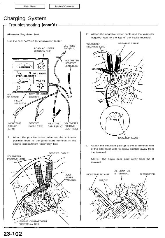
Charging System Troubleshooting Alternator/Regulator Test Use the SUN VAT-40 (or equivalent) tester. 2. Attach the negative tester cable and the voltmeter negative lead to the top of the intake manifold. LOAD ADJUSTER (CARBON PILE) FULL FIELD LEAD (BLU) VOLTMETER NEGATIVE LEAD (BLK) VOLT SELECTOR FIELD SELECTOR INDUCTIVE PICK-UP (GRN) POSITIVE CABLE (RED) NEGATIVE CABLE (BLK) […]

Categories
Fuel & Emissions

nsxb11059a.pdf

PGM-FI System System Description PGM-FI System The PGM-FI system on this model is a sequential multiport fuel injection system. Fuel Injector Timing and Duration The ECM contains memories for the basic discharge durations at various engine speeds and manifold pressures. The basic discharge duration, after being read out from the memory, is further modified by […]

Categories
Brakes & ABS

nsxb19012a.pdf

Master Cylinder and Brake Booster Index/Torque BRAKE BOOSTER Do not disassemble. Tests, page 19-14 Pushrod Clearance Adjustment, page 19-15 MASTER CYLINDER Inspection, page 19-13 Attachments nsxb19012a (47 kB)

Categories
Electrical

nsxe23270a.pdf

CAUTION: All SRS electrical wiring harnesses are covered with yellow outer insulation. Before disconnecting the SRS wire harness, install the short connector on the airbag (see page 23-323). Replace the entire affected SRS harness assembly if it has an open circuit or damaged wiring. SRS MAIN WIRE HARNESS DEFOGGER SWITCH Removal, page 23-273 Test, page […]

Categories
Suspension

nsxb18002a.pdf

Special Tools 18-33, 18-34 18-18, 18-34 18-18, 18-33 18-26, 18-39 18-21, 18-22, 18-24, 18-37 18-21, 18-36 18-26 18-18 , 18-34 18-39 Mam Menu Table of Contents Special Tools Ref. No. Tool Number Description (щ Page Reference ® O7GAF—SD401OO Hub Dis/Assembly Pin l 1 18-33, 18-34 @ 07GAF—SD40200 Hub Assembly Driver Attachment ‘1 18-18. 18-34 © […]

Categories
Heating, Ventilation and Air Conditioning

nsxb22061a.pdf

In-car Temperature Sensor Removal The in-car temperature sensor assembly includes a small fan (aspirator fan) to draw air past the sensor (see page 22-66(’93-’96), 91(’91-’92)). SRS components are located in this area. Review the SRS component locations, precautions, and procedures in the SRS section (24) before performing repairs or service. 1. Remove the center console […]

Categories
Specifications

nsxb03011a.pdf

Differential (Manual Transmission) — Section 15 Differential (Automatic Transmission) — Section 15 Main Menu Table of Contents — Differential (Manual Transmission) — Section 15 MEASUREMENT STANDARD (NEW) SERVICE LIMIT Differential Preset Torque N’m (kg-m, Ib-fl) Assembly 60-140 (6-14, 43-101) 30 (3, 22) carrier V V i V On-carrr 120-2330 (12-28, 87-203) 60 (6, 43) V […]

Categories
Electrical

nsxb23288a.pdf

Rear Window Defogger Function Test CAUTION: Be careful not to scratch or damage the defogger wires with the tester probe. 1. Check for voltage between the positive terminal and body ground with the ignition switch and the defogger switch ON. There should be battery voltage. • If there is no voltage, check for: — Faulty […]

Categories
Fuel & Emissions

nsxb11134a.pdf

Fuel Supply System Fuel Injectors Replacement Do not smoke during the work. Keep open flames away from your work area. 1. Relieve fuel pressure (see page 11-132). 2. Remove the intake manifold covers. 3. Disconnect the connectors from the fuel injectors and the IAT sensor. 4. Disconnect the vacuum hose and fuel return hose from […]

Categories
Body

nsxb20004a.pdf

Construction Composition REAR HATCH FRAME TRUNK LID (#6000) HOOD (#6000) SIDE SILL (#6000) REAR FENDER (#6000) Body Composites (#5000) DOOR (#6000) FRONT FENDER (#6000) Types of aluminum alloys for pressings: ROOF PANEL (#6000) Attachments nsxb20004a (65 kB)