Troubleshooting
Alternator/Regulator Test
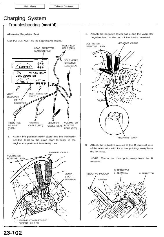
Use the SUN VAT-40 (or equivalent) tester.
2. Attach the negative tester cable and the voltmeter
negative lead to the top of the intake manifold.
LOAD ADJUSTER
(CARBON PILE)
FULL FIELD
LEAD (BLU)
VOLTMETER
NEGATIVE
LEAD (BLK)
VOLT
SELECTOR
FIELD
SELECTOR
INDUCTIVE
PICK-UP
(GRN)
POSITIVE
CABLE (RED)
NEGATIVE
CABLE (BLK)
VOLTMETER
POSITIVE
LEAD (RED)
1. Attach the positive tester cable and the voltmeter
positive lead to the jump start terminal in the
engine compartment fuse/relay box.
POSITIVE CABLE
VOLTMETER
POSITIVE LEAD
JUMP
START
TERMINAL
– ENGINE COMPARTMENT
FUSE/RELAY BOX
VOLTMETER
NEGATIVE LEAD
NEGATIVE CABLE
NEGATIVE MARK
3. Attach the inductive pick-up to the B terminal wire
of the alternator with its arrow pointing away from
the terminal.
NOTE: The arrow must point away from the B
terminal.
INDUCTIVE PICK-UP
ARROW
ALTERNATOR
B TERMINAL ALTERNATOR
TEST SELECTOR
SWITCH
NOTE: Be sure the battery is sufficiently charged
(see page 23-68).
Connect the Sun VAT-40 (see
page 23-102) and turn the selec-
tor switch to position 1 (star-
ting).
Start the engine and let it idle un-
til it reaches normal operating
temperature.
Raise the engine speed to 2,000
rpm and hold it there.
Is the voltage over 15.1 V?
Release the accelerator pedal
and let the engine idle.
Make sure all accessories are
turned off. Turn the selector
switch to position 2 (charging).
Remove the inductive pick-up
and zero the ammeter.
Attach the inductive pick-up to
the B terminal wire of the
alternator with its arrow pointing
away from the terminal.
Raise the engine speed to 2,000
rpm and hold it there.
Is the voltage less than 13.9 V?
(To page 23-104)
Replace the voltage regulator.
Test the battery (see page
23-68).
Charging System
Troubleshooting
(From page 23-103)
Apply a load with the VAT-40
until the battery voltage drops to
between 12-13.5 V.
Is the amperage 85 A or more?
With the engine speed still at
2,000 rpm, full-field the alter-
nator.
Turn the ignition switch off.
Disconnect the 4-P connector
from the alternator.
Turn the ignition switch ON (II).
Check for voltage in the YEL wire
at the IG terminal and in the
WHT/GRN wire at the S terminal
of the 4-P connector.
Is there battery voltage in both
wires?
Charging system is OK.
NOTE: Attach a probe to the VAT-40 full-field test
lead, and insert the probe into the full-field access
hole at the back of the alternator. Switch the field
selector to “A (Ground)” position momentarily, and
check the amperage reading.
CAUTION: The voltage will rise quickly when the
alternator is full-fielded. Do not let it exceed 18V
or you may damage the electrical system.
FULL-FIELD ACCESS HOLE
END COVER
REGULATOR
(Located inside the end cover
Is the alternator output 85 A or
more?
Test and repair the alternator
(see page 23-106).
IG (YEL)
S (WHT/GRN)
Repair open in the YEL wire or the
WHT/GRN wire.
Replace the voltage regulator.