Category: Electrical
Categories
nsxe23294a.pdf
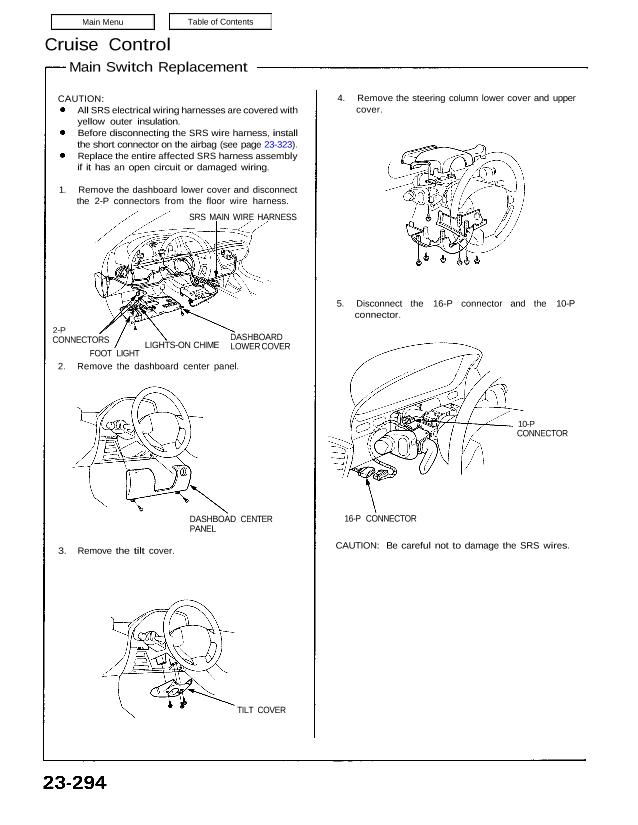
Cruise Control Main Switch Replacement CAUTION: All SRS electrical wiring harnesses are covered with yellow outer insulation. Before disconnecting the SRS wire harness, install the short connector on the airbag (see page 23-323). Replace the entire affected SRS harness assembly if it has an open circuit or damaged wiring. 1. Remove the dashboard lower cover […]
Categories
nsxb23073a.pdf
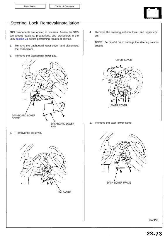
Steering Lock Removal/Installation SRS components are located in this area. Review the SRS component locations, precautions, and procedures in the SRS section 24 before performing repairs or service. 1. Remove the dashboard lower cover, and disconnect the connectors. 2. Remove the dashboard lower pad. DASHBOARD LOWER COVER 3. Remove the tilt cover. DASHBOARD LOWER PAD […]
Categories
nsxb23102a.pdf
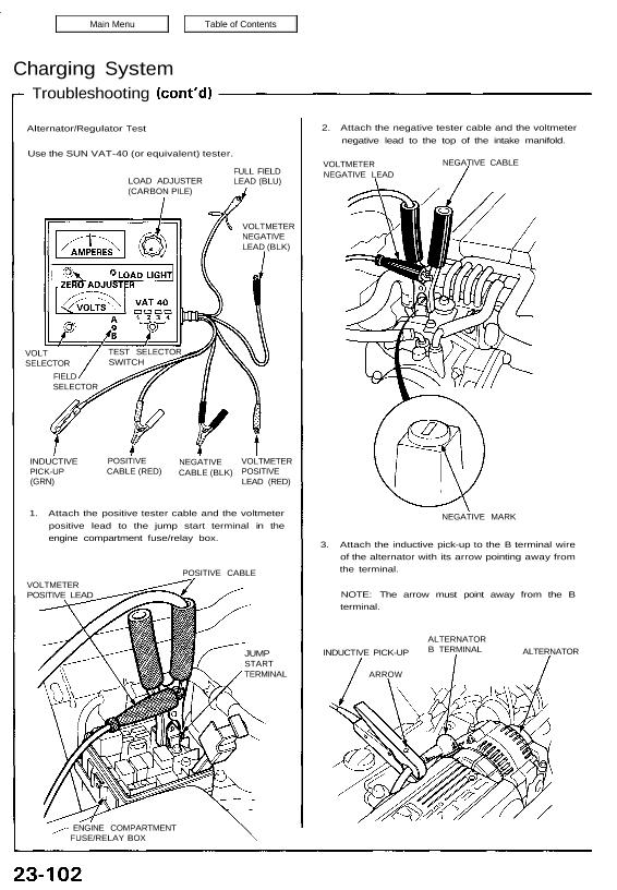
Charging System Troubleshooting Alternator/Regulator Test Use the SUN VAT-40 (or equivalent) tester. 2. Attach the negative tester cable and the voltmeter negative lead to the top of the intake manifold. LOAD ADJUSTER (CARBON PILE) FULL FIELD LEAD (BLU) VOLTMETER NEGATIVE LEAD (BLK) VOLT SELECTOR FIELD SELECTOR INDUCTIVE PICK-UP (GRN) POSITIVE CABLE (RED) NEGATIVE CABLE (BLK) […]
Categories
nsxe23270a.pdf
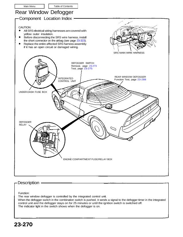
CAUTION: All SRS electrical wiring harnesses are covered with yellow outer insulation. Before disconnecting the SRS wire harness, install the short connector on the airbag (see page 23-323). Replace the entire affected SRS harness assembly if it has an open circuit or damaged wiring. SRS MAIN WIRE HARNESS DEFOGGER SWITCH Removal, page 23-273 Test, page […]
Categories
nsxb23288a.pdf
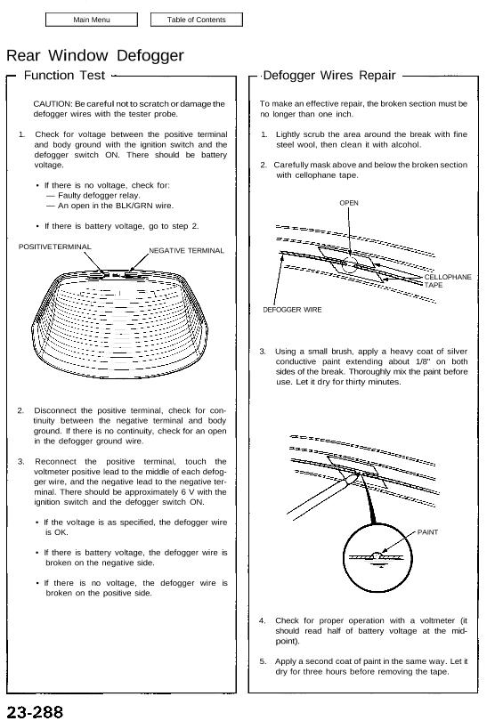
Rear Window Defogger Function Test CAUTION: Be careful not to scratch or damage the defogger wires with the tester probe. 1. Check for voltage between the positive terminal and body ground with the ignition switch and the defogger switch ON. There should be battery voltage. • If there is no voltage, check for: — Faulty […]
Categories
nsxb23129a.pdf
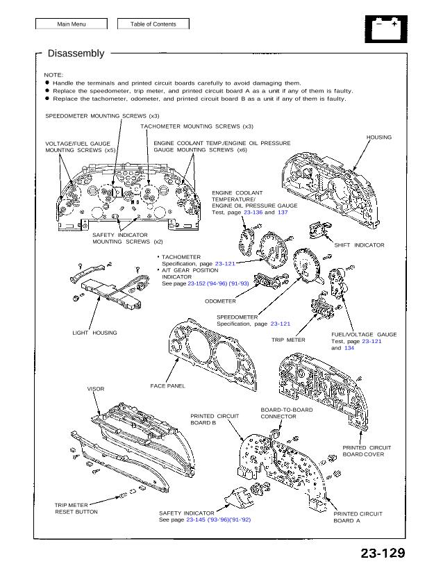
Disassembly NOTE: Handle the terminals and printed circuit boards carefully to avoid damaging them. Replace the speedometer, trip meter, and printed circuit board A as a unit if any of them is faulty. Replace the tachometer, odometer, and printed circuit board B as a unit if any of them is faulty. SPEEDOMETER MOUNTING SCREWS (x3) […]
Categories
nsxb23115a.pdf
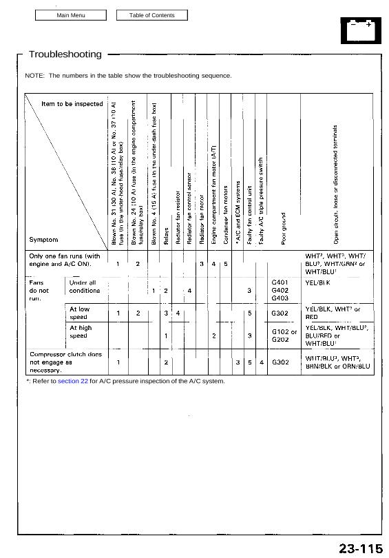
Troubleshooting NOTE: The numbers in the table show the troubleshooting sequence. *: Refer to section 22 for A/C pressure inspection of the A/C system. Attachments nsxb23115a (48 kB)
Categories
nsxb23291a.pdf
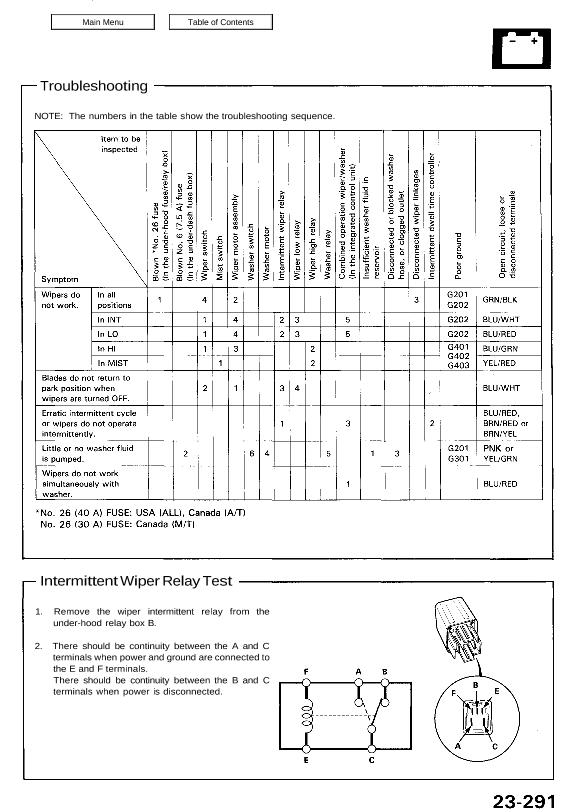
Troubleshooting Intermittent Wiper Relay Test 1. Remove the wiper intermittent relay from the under-hood relay box B. 2. There should be continuity between the A and C terminals when power and ground are connected to the E and F terminals. There should be continuity between the B and C terminals when power is disconnected. NOTE: […]
Categories
nsxe23208a.pdf
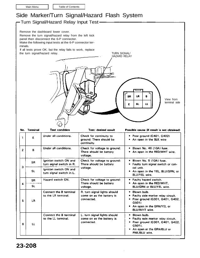
Side Marker/Turn Signal/Hazard Flash System Turn Signal/Hazard Relay Input Test Remove the dashboard lower cover. Remove the turn signal/hazard relay from the left kick panel then disconnect the 6-P connector. Make the following input tests at the 6-P connector ter- minals. If all tests prove OK, but the relay fails to work, replace the turn […]
Categories
nsxd23130a.pdf
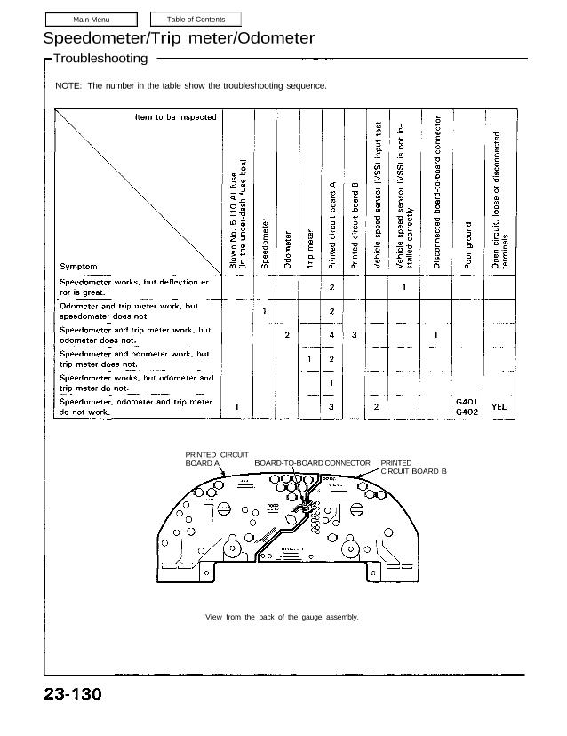
View from the back of the gauge assembly. PRINTED CIRCUIT BOARD A BOARD-TO-BOARD CONNECTOR PRINTED CIRCUIT BOARD B NOTE: The number in the table show the troubleshooting sequence. Speedometer/Trip meter/Odometer Troubleshooting NOTE: A short to ground in the ORN wire can be caused by a short in any component connected to it. Vehicle Speed Sensor […]