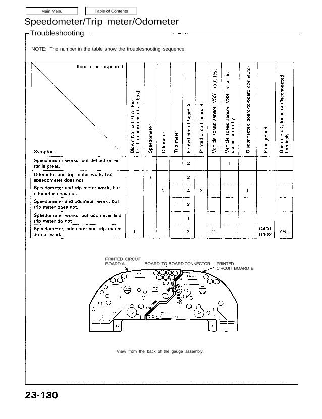
PRINTED CIRCUIT
BOARD A BOARD-TO-BOARD CONNECTOR PRINTED
CIRCUIT BOARD B
NOTE: The number in the table show the troubleshooting sequence.
Speedometer/Trip meter/Odometer
Troubleshooting
NOTE: A short to ground in the ORN wire can be caused by a short in any component connected to it.
Vehicle Speed Sensor (VSS) Test
Speedometer does not work.
Inspect No. 2 (15 A) fuse in the
under-dash fuse box before
testing.
Disconnect the 3-P connector at
the VSS.
Turn the ignition switch ON.
Measure voltage between the
BLK/YEL wire terminal and the
BLK wire terminal in the harness
side of the 3-P connector.
Is there battery voltage?
Measure voltage between the
YEL/RED and the BLK wire ter-
minals.
Is there about 5 V?
(To next page)
Repair open in YEL/RED wire or
short to body ground.
View from
terminal side
3-P CONNECTOR
VSS
BLK
Is there continuity?
Repair open BLK/YEL wire, be-
tween the VSS and under-dash
fuse box.
Check for continuity between the
BLK terminal and body ground.
Repair open between
the VSS and ground
G101.
(cont’d)
Speedometer/Trip Meter/Odometer
Troubleshooting (cont’d)
(From previous page)
Reconnect the 3-P connector at
the vehicle speed sensor (VSS).
Raise the rear of the car and sup-
port it with stands.
Back-probe the YEL/RED wire and
connect it to body ground through
a voltmeter.
Put the car in neutral with key ON.
Slowly rotate one wheel with the
other wheel blocked.
Does voltage pulse from 0 to
about 12 V?
Disconnect the 30-P connector at
the speedometer.
Back-probe the YEL/RED wire and
connect it to body ground through
a voltmeter.
Slowly rotate one wheel with the
other wheel blocked.
Does the volt meter indicate
pulsing voltage?
Replace the speedometer.
Repair open in the YEL/RED wire,
between the VSS and the
speedometer.
Replace the VSS (see page
23-133).