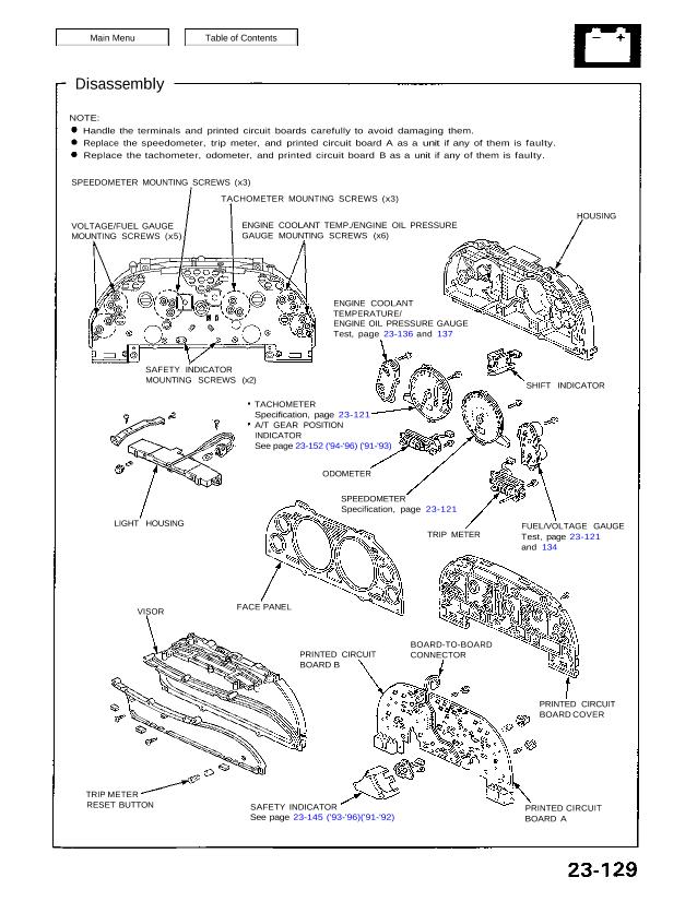
Disassembly
NOTE:
Handle the terminals and printed circuit boards carefully to avoid damaging them.
Replace the speedometer, trip meter, and printed circuit board A as a unit if any of them is faulty.
Replace the tachometer, odometer, and printed circuit board B as a unit if any of them is faulty.
SPEEDOMETER MOUNTING SCREWS (x3)
TACHOMETER MOUNTING SCREWS (x3)
VOLTAGE/FUEL GAUGE
MOUNTING SCREWS (x5)
ENGINE COOLANT TEMP./ENGINE OIL PRESSURE
GAUGE MOUNTING SCREWS (x6)
HOUSING
ENGINE COOLANT
TEMPERATURE/
ENGINE OIL PRESSURE GAUGE
Test, page 23-136 and 137
SAFETY INDICATOR
MOUNTING SCREWS (x2) SHIFT INDICATOR
TACHOMETER
Specification, page 23-121
A/T GEAR POSITION
INDICATOR
See page 23-152 (’94-’96) (’91-’93)
LIGHT HOUSING
ODOMETER
SPEEDOMETER
Specification, page 23-121
TRIP METER
FUEL/VOLTAGE GAUGE
Test, page 23-121
and 134
FACE PANEL
PRINTED CIRCUIT
BOARD B
BOARD-TO-BOARD
CONNECTOR
PRINTED CIRCUIT
BOARD COVER
PRINTED CIRCUIT
BOARD A
SAFETY INDICATOR
See page 23-145 (’93-’96)(’91-’92)
TRIP METER
RESET BUTTON
VISOR