SRS components are located in this area. Review the SRS
component locations, precautions, and procedures in the
SRS section 24 before performing repairs or service.
1. Remove the dashboard lower cover, and disconnect
the connectors.
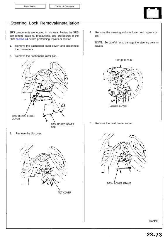
2. Remove the dashboard lower pad.
DASHBOARD LOWER
COVER
3. Remove the tilt cover.
DASHBOARD LOWER
PAD
TILT COVER
4. Remove the steering column lower and upper cov-
ers.
NOTE: Be careful not to damage the steering column
covers.
UPPER COVER
LOWER COVER
5. Remove the dash lower frame.
DASH LOWER FRAME
Ignition Switch
Steering Lock Removal/Installation
6. Disconnect the ignition switch 7-P and 8-P connec-
tors.
7. Remove the column holder mounting bolts and the
mounting nuts, and lower the steering column
assembly.
CAUTION: Be careful not to damage the SRS wire
harness.
16 N-m
(1.6 kg-m, 12 Ib-ft)
39 N-m
(3.9 kg-m, 28 Ib-ft)
8. Center-punch the shear bolt, and drill its head off
with a 5 mm (3/16 in) drill bit.
CAUTION: Do not damage the switch body.
9. Remove the shear bolt from the switch body.
10. Insert the key, and turn it to “I”.
11. Push the lock pin, and pull out the steering lock
assembly.
STEERING LOCK
BODY
Installation:
1. Turn the key to “I”, push the pin, and insert the
steering lock assembly into the steering column
until it clicks into place.
2. Loosely tighten the new shear bolt. Make sure the
projection on the ignition switch is aligned with the
hole in the steering column.
3. Insert the ignition key, and check for proper opera-
tion of the steering wheel lock and that the ignition
key turns freely.
4. Tighten the shear bolt until the hex head twists off.
SHEAR BOLT
/
TWIST-OFF PORTION