Categories
Manual Transmission

nsxb13032a.pdf

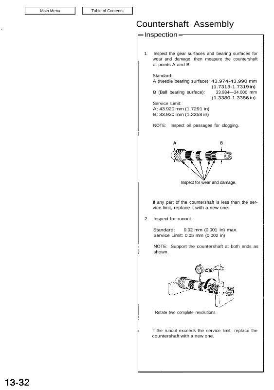
Countershaft Assembly Inspection 1. Inspect the gear surfaces and bearing surfaces for wear and damage, then measure the countershaft at points A and B. Standard: A (Needle bearing surface): 43.974-43.990 mm (1.7313-1.7319 in) B (Ball bearing surface): 33.984—34.000 mm (1.3380-1.3386 in) Service Limit: A: 43.920 mm (1.7291 in) B: 33.930 mm (1.3358 in) NOTE: Inspect […]

Categories
Differential

nsxb15004a.pdf

Preset Torque Inspection On-Car: 1. Block the front wheels. 2. Shift to low gear. 3. Lift up rear wheels, and place the safety stand (Lift and Support Points, see section 1). 4. Measure preset torque clockwise using a torque wrench as shown. Standard: 120-280 N-m (12-28 kg-m, 87-203 Ib-ft) Service Limit: 60 N-m (6 kg-m, […]

Categories
Electrical

nsxe23146a.pdf

Safety Indicator Troubleshooting NOTE: The numbers in the table show the troubleshooting sequence. Main Menu Table of Contents Safety Indicator Troubleshooting NOTE: The numbers in the table show the troubleshooting sequence. Item to be inspected Blown No. 5 (10 A) fuse (in the under-dash fuse box] Blown No. 34 (15 A) fuse (in the under-dash […]

Categories
Electrical

nsxd23311a.pdf

Troubleshooting NOTE: The numbers in the table show the troubleshooting sequence. Main Menu Table of Contents Troubleshooting NOTE: The numbers in the table show the troubleshooting sequence. Item to be Inspected „Eg L Een-9 ≞∖ me). nux ggg ≣≝≣ .c en: Ф .i: o ⋅≔⋮⊙ :gg 0.:: ↼∙ ∙∙ „‚ .. _ ↩ ⋅− :o: […]

Categories
Fuel & Emissions

nsxb11038a.pdf

Troubleshooting Troubleshooting Procedures I. How To Begin Troubleshooting When the Malfunction Indicator Lamp (MIL) has been reported on, or there is a driveability problem, use the appropri- ate procedure below to diagnose and repair the problem. MALFUNCTION INDICATOR LAMP (MIL) A. When the MIL has come on: 1. Connect the Honda PGM Tester or an […]

Categories
Electrical

nsxb23286a.pdf

Rear Window Defogger Relay Test 1. Remove the defogger relay in the engine compart- ment fuse/relay box. 2. Check continuity at the relay terminals. There should be continuity between the C and D terminals. There should be continuity between the A and B terminals when power and ground are connected to the C and D […]

Categories
Electrical

nsxb23287a.pdf

Switch Test 1. Remove the dashboard lower cover (see page 23-285). 2. If necessary, remove the dashboard lower pad. 3. Disconnect the 18-P connector from the floor wire harness. 4. Check for continuity between the terminals in each switch position according to the table. REAR WINDOW DEFOGGER SWITCH 18-P CONNECTOR View from wire side Attachments […]

Categories
Electrical

nsxb23323a.pdf

Trunk Latch Switch Test 1. Open the trunk lid and remove the trunk rear trim panel. 2. Disconnect the 3-P connector from the trunk latch. TRUNK LATCH LOCK ROD TRUNK OPENER CABLE View from wire side 3-P CONNECTOR 3. Check continuity at the trunk latch connector termi- nals. • There should be continuity between the […]

Categories
Fuel & Emissions

nsxe11002a.pdf

Special Tools Special Tools Page Reference 11-44, 114, 118, 120, 129, 137, 140 11-21, 32, 37 11-21 11-131 11-21 11-139, 140 11-88 Tool Number A973X-041-XXXXX KS-AHM-32-003 07LAJ-PT3010A 07LAJ-PT30200 07MAJ-PR70100 07JAZ-001000A 07406-0040001 Main Menu Table of Contents Special Tools — Special Tools Ref. No. Tool Number Description Qty Page Reference ® A973X—041—XXXXX Vacuum Pump/Gauge 1 11-44, […]

Categories
Electrical

nsxb23271a.pdf

NOTE: The numbers in the table show the troubleshooting sequence. Troubleshooting Main Menu Table of Contents Troubleshooting NOTE: The numbers in the table show the troubleshooting sequence. Item to be inspected In the under- hood fuse/ relay box Blown No. 5 (15 A) fuse (In the under-dash fuse box) Blown No. 34 (15 A) fuse […]