Categories
Electrical

nsxb23269a.pdf

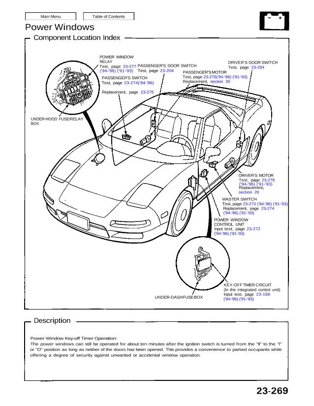
Power Windows Component Location Index POWER WINDOW RELAY Test, page 23-277 (’94-’96) (’91-’93) PASSENGER’S SWITCH Test, page 23-274(’94-’96) Replacement, page 23-275 PASSENGER’S DOOR SWITCH Test, page 23-204 PASSENGER’S MOTOR Test, page 23-276(’94-’96) (’91-’93) Replacement, section 20 DRIVER’S DOOR SWITCH Test, page 23-204 DRIVER’S MOTOR Test, page 23-276 (’94-’96) (’91-’93) Replacement, section 20 MASTER SWITCH Test, […]

Categories
Manual Transmission

nsxd13006a.pdf

Transmission Assembly Removal CAUTION: Use fender covers to avoid damaging painted surfaces. 1. Check and record the rear wheel alignment (see section 18). 2. Disconnect the battery negative (—), and positive (+) cables from the battery. 3. Drain transmission oil. Reinstall the drain plug with a new washer. Corrosion resistant bolt/nut 4. Remove the strut […]

Categories
Electrical

nsxb23255a.pdf

Power Mirrors Component Location Index RIGHT MIRROR Test, page 23-259 Replacement, page 23-259 LEFT MIRROR Test, page 23-259 Replacement, page 23-259 POWER MIRROR SWITCH Function Test, page 23-257 Removal, page 23-258 Test, page 23-258 UNDER-DASH FUSE BOX Attachments nsxb23255a (47 kB)

Categories
Automatic Transmission

nsxd14143a.pdf

OIL GUIDE PLATE Replace. 0–0.05 mm (0–0 .002 in) ATTACHMENT, 62 x 68 mm 07746–0010500 BEARING OIL GUIDE PLATE Replace. 0–0.05 mm (0–0.002 in) ATTACHMENT, 72 x 75 mm 07746–0010600 BEARING DRIVER 07749–0010000 2. Replace the oil guide plate. 3. Drive the new bearing into the housing using the spe- cial tools as shown. COUNTERSHAFT […]

Categories
Automatic Transmission

nsxd14132a.pdf

Clutch Illustrated Index 1ST CLUTCH 4TH CLUTCH SNAP RING CLUTCH END PLATE CLUTCH DISCS Standard thickness: 2.34 mm (0.092 in) CLUTCH PLATES Standard thickness: 2.3mm (0.091 in) CLUTCH DRUM O-RINGS Replace. CLUTCH PISTON RETURN SPRING SPRING RETAINER CIRCLIP CLUTCH DISCS Standard thickness: 1.94 mm (0.076 in) CIRCLIP SPRING RETAINER RETURN SPRING CLUTCH PISTON O-RINGS Replace. […]

Categories
Fuel & Emissions

nsxb11026a.pdf

System Description System Connectors [Engine Compartment (Left Side)] Main Menu Table of Contents System Description System Connectors [Engine Compartment (Left Side)] (cont’d) ENGWE WIRE HARNESS C120 J» / −↗⋯ it c123 _ ∣ ∁↿↿∍ più” ⋡↽≓≓ C109 ∙ c540 A r` c110 I 0″” _ O `v c111 ↽ ≓−⇖⋅⋅⋡ X ∎ ∖↜∖ c113 ‚_— […]

Categories
Automatic Transmission

nsxd14079a.pdf

Lock-up Control Solenoid Valve A/B Test NOTE: Lock-up control solenoid valves A and B must be removed/replaced as an assembly. 1. Disconnect the connector from the lock-up control solenoid valve A/B. 2. Measure the resistance between the No. 1 terminal (solenoid valve A) of the lock-up control solenoid valve connector and body ground and between […]

Categories
Automatic Transmission

nsxd14124a.pdf

O-RINGS Replace. 3RD CLUTCH ASSEMBLY 3RD GEAR COLLAR PARKING GEAR RETAINER PLATE 1ST GEAR COLLAR NEEDLE BEARINGS 34 x 40 x 20 mm ONE-WAY CLUTCH 1ST GEAR 1ST-HOLD CLUTCH HUB THRUST NEEDLE BEARING THRUST WASHER O-RINGS Replace. 1ST-HOLD CLUTCH ASSEMBLY LOCKNUT Replace. 140 N·m (14.0 kg-m, 101 Ib-ft)CONICAL SPRING REVERSE GEAR COLLAR THRUST WASHER REVERSE […]

Categories
Electrical

nsxd23073a.pdf

Steering Lock Removal/Installation SRS wire harness is routed near the steering lock assembly. CAUTION: All SRS wiring harnesses are covered with yellow outer insulation. Before disconnecting any part of the SRS wire harness, install the short connectors (see page 23-328). Replace the entire affected SRS harness assembly if it has an open circuit or damaged […]

Categories
Maintenance

nsxe04004a.pdf

SEC & PAGE NOTES 11-112 11-84 11-125 11-128 11-135 23-89 11-134 6-54 (’91-’93) 11-4, 97 11-4 23-94 8-4 8-5 23-107 10-2, 3 10-5 13-3 14-94 (’91-’93) R = Replace I = Inspect After inspection, clean, adjust, repair or replace if necessary. Check oil and coolant level at each fuel stop. Under severe driving conditions, service […]