Lock-up Control Solenoid Valve A/B
Test
NOTE: Lock-up control solenoid valves A and B must be
removed/replaced as an assembly.
1. Disconnect the connector from the lock-up control
solenoid valve A/B.
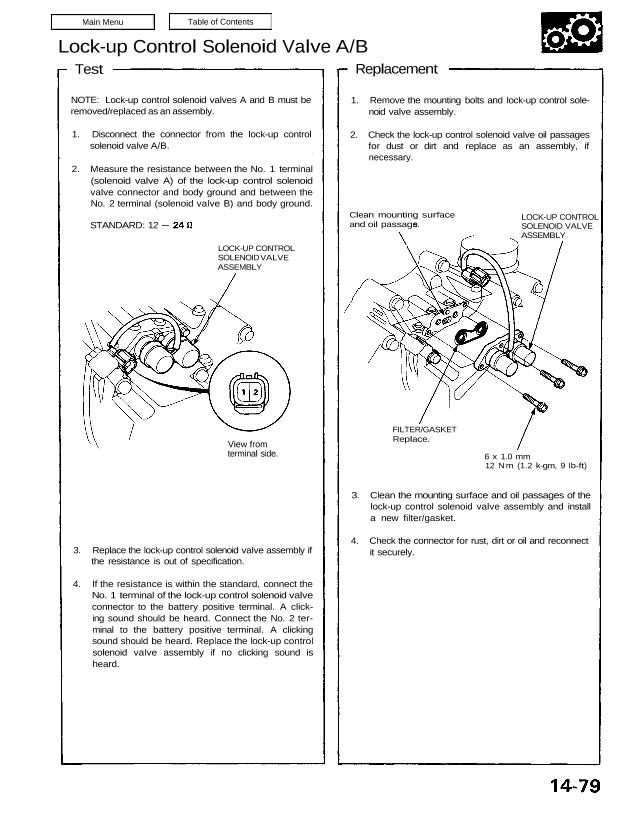
2. Measure the resistance between the No. 1 terminal
(solenoid valve A) of the lock-up control solenoid
valve connector and body ground and between the
No. 2 terminal (solenoid valve B) and body ground.
View from
terminal side.
3. Replace the lock-up control solenoid valve assembly if
the resistance is out of specification.
4. If the resistance is within the standard, connect the
No. 1 terminal of the lock-up control solenoid valve
connector to the battery positive terminal. A click-
ing sound should be heard. Connect the No. 2 ter-
minal to the battery positive terminal. A clicking
sound should be heard. Replace the lock-up control
solenoid valve assembly if no clicking sound is
heard.
3. Clean the mounting surface and oil passages of the
lock-up control solenoid valve assembly and install
a new filter/gasket.
4. Check the connector for rust, dirt or oil and reconnect
it securely.
6 x 1.0 mm
12 N.m (1.2 k-gm, 9 Ib-ft)
FILTER/GASKET
Replace.
LOCK-UP CONTROL
SOLENOID VALVE
ASSEMBLY
Clean mounting surface
and oil passages.
1. Remove the mounting bolts and lock-up control sole-
noid valve assembly.
2. Check the lock-up control solenoid valve oil passages
for dust or dirt and replace as an assembly, if
necessary.
Replacement
STANDARD: 12
LOCK-UP CONTROL
SOLENOID VALVE
ASSEMBLY
Test
NOTE: Lock-up control solenoid valves A and B must be
removed/replaced as an assembly.
1. Disconnect the connector from the lock-up control
solenoid valve A/B.
2. Measure the resistance between the No. 1 terminal
(solenoid valve A) of the lock-up control solenoid
valve connector and body ground and between the
No. 2 terminal (solenoid valve B) and body ground.
View from
terminal side.
3. Replace the lock-up control solenoid valve assembly if
the resistance is out of specification.
4. If the resistance is within the standard, connect the
No. 1 terminal of the lock-up control solenoid valve
connector to the battery positive terminal. A click-
ing sound should be heard. Connect the No. 2 ter-
minal to the battery positive terminal. A clicking
sound should be heard. Replace the lock-up control
solenoid valve assembly if no clicking sound is
heard.
3. Clean the mounting surface and oil passages of the
lock-up control solenoid valve assembly and install
a new filter/gasket.
4. Check the connector for rust, dirt or oil and reconnect
it securely.
6 x 1.0 mm
12 N.m (1.2 k-gm, 9 Ib-ft)
FILTER/GASKET
Replace.
LOCK-UP CONTROL
SOLENOID VALVE
ASSEMBLY
Clean mounting surface
and oil passages.
1. Remove the mounting bolts and lock-up control sole-
noid valve assembly.
2. Check the lock-up control solenoid valve oil passages
for dust or dirt and replace as an assembly, if
necessary.
Replacement
STANDARD: 12
LOCK-UP CONTROL
SOLENOID VALVE
ASSEMBLY