Steering Lock Removal/Installation
SRS wire harness is routed near the steering lock
assembly.
CAUTION:
All SRS wiring harnesses are covered with
yellow outer insulation.
Before disconnecting any part of the SRS wire
harness, install the short connectors (see page
23-328).
Replace the entire affected SRS harness
assembly if it has an open circuit or damaged
wiring.
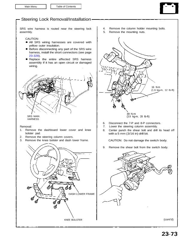
4. Remove the column holder mounting bolts.
5. Remove the mounting nuts.
39 N·m
(3.9 kg-m, 28 Ib-ft)
16 N·m
(1.6 kg-m, 12 Ib-ft)
6. Disconnect the 7-P and 8-P connectors.
7. Lower the steering column assembly.
8. Center punch the shear bolt and drill its head off
with a 5 mm (3/16 in) drill bit.
CAUTION: Do not damage the switch body.
9. Remove the shear bolt from the switch body.
(cont’d)
Removal:
1. Remove the dashboard lower cover and knee
bolster pad.
2. Remove the steering column covers.
3. Remove the knee bolster and dash lower frame.
KNEE BOLSTER
DASH LOWER FRAME
SRS MAIN
HARNESS
SRS wire harness is routed near the steering lock
assembly.
CAUTION:
All SRS wiring harnesses are covered with
yellow outer insulation.
Before disconnecting any part of the SRS wire
harness, install the short connectors (see page
23-328).
Replace the entire affected SRS harness
assembly if it has an open circuit or damaged
wiring.
4. Remove the column holder mounting bolts.
5. Remove the mounting nuts.
39 N·m
(3.9 kg-m, 28 Ib-ft)
16 N·m
(1.6 kg-m, 12 Ib-ft)
6. Disconnect the 7-P and 8-P connectors.
7. Lower the steering column assembly.
8. Center punch the shear bolt and drill its head off
with a 5 mm (3/16 in) drill bit.
CAUTION: Do not damage the switch body.
9. Remove the shear bolt from the switch body.
(cont’d)
Removal:
1. Remove the dashboard lower cover and knee
bolster pad.
2. Remove the steering column covers.
3. Remove the knee bolster and dash lower frame.
KNEE BOLSTER
DASH LOWER FRAME
SRS MAIN
HARNESS
Ignition Switch
Steering Lock Removal/Installation (cont’d)
10. Insert the key and turn it to “I”.
STEERING LOCK
BODY
11. Push the lock pin and pull out the steering lock
assembly.
TWIST-OFF PORTION
SHEAR BOLT
Installation:
1. Turn the key to “I”, push the pin and insert the
steering lock assembly into the steering column un-
til it clicks into place.
2. Loosely tighten the new shear bolt. Make sure the
projection on the ignition switch is aligned with the
hole in the steering column.
3. Insert the ignition key and check for proper opera-
tion of the steering wheel lock and that the ignition
key turns freely.
4. Tighten the shear bolt until the hex head twists off.