Categories
Heating, Ventilation and Air Conditioning

nsxb22070a.pdf

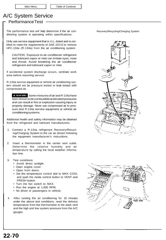
A/C System Service Performance Test The performance test will help determine if the air con- ditioning system is operating within specifications. Only use service equipment that is U.L.-listed and is cer- tified to meet the requirements of SAE J2210 to remove HFC-134a (R-134a) from the air conditioning system. CAUTION: Exposure to air conditioner refrigerant and […]

Categories
Electrical

nsxe23127a.pdf

Speedo/Tripmeter/Odometer Troubleshooting NOTE: The numbers in the table show the troubleshooting sequence. PRINTED CIRCUIT PANEL A JOINT CONNECTOR PRINTED CIRCUIT PRINEL B View from the back of the gauge assembly. Attachments nsxe23127a (157 kB)

Categories
Manual Transmission

nsxb13014a.pdf

Reverse Idler Gear Shaft Assembly Removal 1. Remove the reverse shift arm from the clutch housing. REVERSE SHIFT ARM CLUTCH HOUSING 2. Shift the reverse shift fork to the driven gear side. 3. Lift the mainshaft assembly and reverse idler gear shaft assembly, then remove the reverse shift fork assembly. REVERSE SHIFT FORK ASSEMBLY 4. […]

Categories
Electrical

nsxb23274a.pdf

Power Windows Passenger’s Switch Test 1. Remove the door panel (see section 20). 2. Disconnect the 8-P connector. View from wire side 3. Check for continuity between the terminals in each switch position according to the table. Master Switch Replacement 1. Remove the door panel (see section 20). 2. Remove the four screws, then remove […]

Categories
Electrical

nsxd23215a.pdf

Hazard Warning Switch Light Bulb Replacement 1. Remove the steering column covers. 2. Remove the screws from the hazard warning and wiper switches. HAZARD WARNING SWITCH 3. Remove the two screws from the back of switch. HAZARD WARNING SWITCH 4. Slide the hazard warning switch out of the housing as shown. 5. Remove the bulb […]

Categories
Fuel & Emissions

nsxe11140a.pdf

Emission Control System Evaporative Emission Controls (cont’d) Two-Way Valve Test 1. Remove the fuel filler cap. 2. Remove vapor line from the fuel tank and connect to T-fitting from vacuum gauge and vacuum pump as shown. VACUUM/PRESSURE GAUGE 0-4 in. Hg 07JAZ–001000A VACUUM PUMP/ GAUGE A973X–041–XXXXX T—FITTING 3. Apply vacuum slowly and continuously while watching […]

Categories
Fuel & Emissions

nsxe11087a.pdf

System Description Fuel Pressure The fuel supply system consists of a fuel tank, in-tank high pressure fuel pump, fuel pump relay, fuel pump resistor, main relay, fuel filter, pressure regulator, injec- tors and injector resistor. This system delivers pressure regulated fuel to the in- jectors and cuts the fuel delivery when the engine is not […]

Categories
Fuel & Emissions

nsxe11137a.pdf

Troubleshooting Flowchart Inspection of Evaporative Emission Controls PURGE CONTROL DIAPHRAGM VALVE VACUUM PUMP/GAUGE A973X-041-XXXXX Disconnect vacuum hose from the purge control diaphragm valve (on the charcoal canister) and connect a vacuum gauge to the hose. Start the engine and allow it to idle. NOTE: Engine coolant tempera- ture must be below 70°C (158°F). Is there […]

Categories
Fuel & Emissions

nsxd11105b.pdf

System Description The fuel supply system consists of a fuel tank, in-tank high pressure fuel pump, fuel pump relay, fuel pump resistor, PGM-FI main relay, fuel filter, fuel pressure regulator, fuel injectors and fuel injector resistor. This system delivers pressure-regulated fuel to the fuel injectors and cuts the fuel delivery when the engine is not […]

Categories
Construction & Function

nsxd05002a.pdf

Outline Description This engine is a 2,977 cm3 (181.6 cu-in) DOHC mid-ship unit having 6 cylinders of 90° —V configuration; it is water cool- ed and equipped with a center plug type pent roof combustion chamber. It is specified for unleaded fuel and uses a PGM-FI system: The PGM-FI system on this model is a […]